38
3. Installation method
NOTE: Do not pry up and down, you can only
rotate the screwdriver.
NOTE: The PCB is mounted in the upper part
of the wired controller. Be careful not to
damage the board with the slot screwdriver.
2. Prepare the following assemblies on the site.
1. This manual provides the installation method of wired controller. Please refer to the wiring diagram of this
installation manual to connect the wire controller with indoor unit.
2. The wired controller works in low voltage loop circuit. Forbid to directly contact the cable of high voltage
above, like 115V,220V,380V, and don’t wire this kind of wire in the said loop; wiring clearance between
confgured tubes should be at the range of 300~500mm or above.
3. The Shielded wire of the wired controller must be grounded frmly.
4. Upon fnish the wire controller connection, do not employed tramegger to detect the insulation.
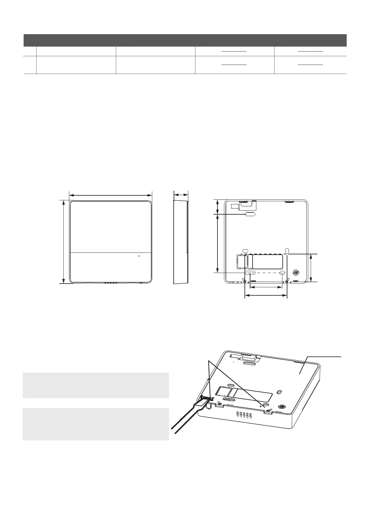
Insert a slot screwdriver into the slots in the
lower part of the wired controller (2 places),
and remove the upper part of the wire controller.
(Fig.3-2)
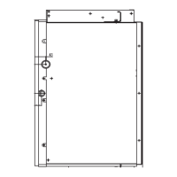
1.Wired remote controller structural dimensions
2.Remove the upper part of wired controller
1
2
1
Switch box
Wiring Tube(Insulating
Sleeve and Tightening Screw)
Qty.(embeded into wall)
No.
Name
Remarks
Specification (only for reference)
1
Fig 3-1
19mm84mm
46mm
60mm
44mm
120mm
120mm
20mm
Back cover
Buckling
position