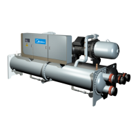
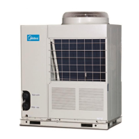
Aqua Tempo Super II
201709 43
Part
4 - Diagnosis and Troubleshooting
Table 4-2.6: Compressor inverter module PCB
Inverter module address switch
Inverter module communication port
V
UV
= V
Uw
= V
VW
0-380V AC
IPM module protection port N2
IPM module protection port P2
Power supply inverter module board
IPM module power supply port N1
IPM module power supply port P1
Three-phase bridge rectifier positive port
Three-phase bridge rectifier control port
Compressor Inverter Module PCB field setting 2.3.1
Table 4-2.7: Compressor inverter module PCB switch settings
000: MC-SU30-RN1L compressor inverter module address setting
000: MC-SU60-RN1L compressor A inverter module address setting
001: MC-SU60-RN1L compressor B inverter module address setting

 Loading...


