8 OVERVIEW OF THE UNIT
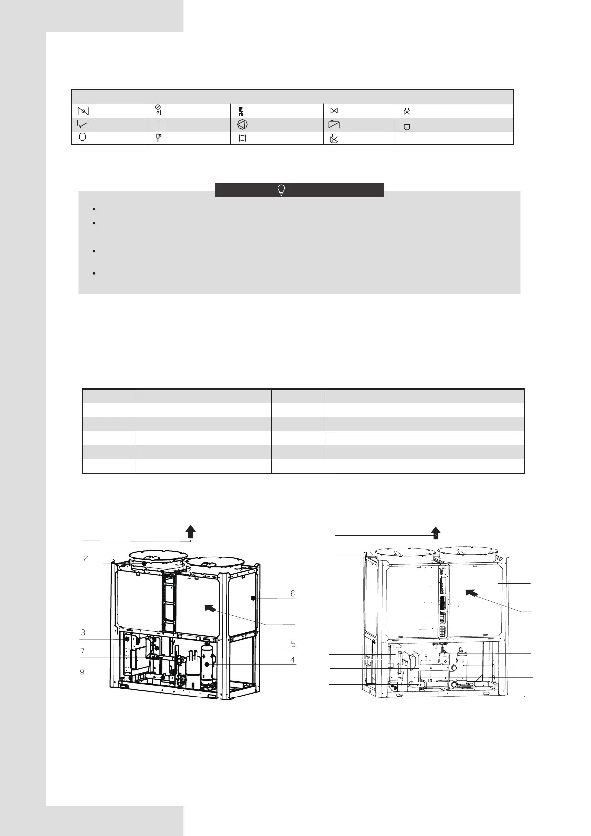
8.1 Main parts of the uint
NO.
1
2
3
4
5
NO.
6
7
8
9
10
NAME
Air outlet
Top cover
Electric control box
Compressor
Evaporator
NAME
Condenser
Water outlet
Air inlet
Water intlet
wire controller (It can be placed indoors)
Symbol explanation
Drain vavle
Y-filter
Expansion tank
Safety valve
Thermometer
Pump
Soft joint
Check valve
Solenoid three-way valve
Atmospheric exhaust valve
Water flow switch
Gate valve
Differential pressure by-pass valve
Water pressure instrument
Fig.7-1 Connection drawing of pipeline system
Table 8-1
NOTE
The ratio of the two - way valves on the terminal shall not exceed 50 percent.
The main outlet water temperature sensing (Tw)head of the unit at address 0 needs to be placed on the main
outlet pipe.
The hot water tank and the hot water exchange pump of the unit use the CN125(220V) port control switch on
the slave board of the 0 # unit, pump output is controlled through CN108(0-10V).
The electromic butterfly valve on the unit water outlet pipe is controlled by the CN123 port on the slave board of each
unit.
11
Fig. 8-2 Main parts of 110KW
1
8
6
2
4
4
3
5
7
9
1
Fig. 8-1 Main parts of 65KW
8
 Loading...