1) Label descriptions are given in Table 8-2
8.3 Outdoor unit PCBs
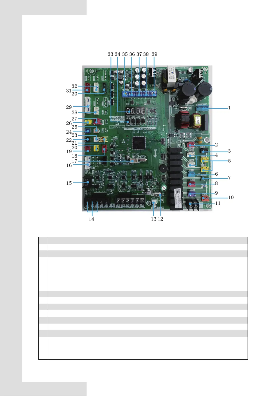
8.3.1 MAIN PCB
Fig. 8-5 Main board of 65KW and 110KW
NO.
1
2
3
4
5
6
7
8
9
10
11
Detail information
CN32:Main board power supply.
Table 8-2
CN99:slave board power supply.
CN75/CN66:EVA-HEAT,Electric of water side heat exchanger heaters connection
CN74/CN67:CCH,Crankcase heater
CN6:ST1,Four-way valve
CN49:SV6,Liquid bypass solenoid valve
CN69:SV5,Multi-function solenoid valve
CN84:SV8A,Injection solenoid valve of compressor system A
CN83:SV8B,Injection solenoid valve of compressor system B
CN93:The alarm signal output of the unit(ON/OFF signal)
Attention: the control port value of the pump actually detected is ON/OFF but not 220-230V control power supply,so
special attention should be paid when installing the alarm signal output.
CN68:Pump(220-240V control power supply )
1)After receiving start-up instruction, the pump will be started up instantly, and will maintain start-up state always
in the process of operation.
2)In case of refrigerating or heating shutdown, the pump will be shut down 2 minutes after all modules stop
operating.
3)In case of shutdown under the pump mode, the pump can be directly shut down.
13
 Loading...