16
8.4 Electric wiring
8.4.1 Electric wiring
CAUTION
The air-conditioner should apply special power supply, whose voltage should conform to rated voltage.
Wiring construction must be conducted by the professional technicians according to the labeling on the circuit
diagram.
The power wire and the grounding wire must be connected to the suitable terminals.
The power wire and the grounding wire must be fasten up by suitable tools.
The terminals connected the power wire and the grounding wire must be fully fastened and regularly checked, in case
to become loose.
Only use the electric components specified by our company, and require installation and technical services from the
manufacturer or authorized dealer. If wiring connection doesn't conform to electric installation specification, it may
cause many troubles like failure on controller, electronic shock and so on.
The connected fixed wires must be equipped with full switching-off devices with at least 3mm contact separation.
Set leakage protective devices according to the requirements of national technical standard about electric equipment.
After completing all wiring construction, conduct careful check before connecting the power supply.
Please carefully read the labels on the electric cabinet.
Please don't repair the controller by yourself, since improper operation may cause electric shock, damages to the
controller and other bad results. If the unit need repair, please contact the maintenance center., since improper repair
may cause electric shock, damages to the controller, and so on. If the user has any requirement of repair, please contact
the maintenance center.
The power cord type designation is H07RN-F.
8.4.2 65KW and 110KW
DSP1 DSP2
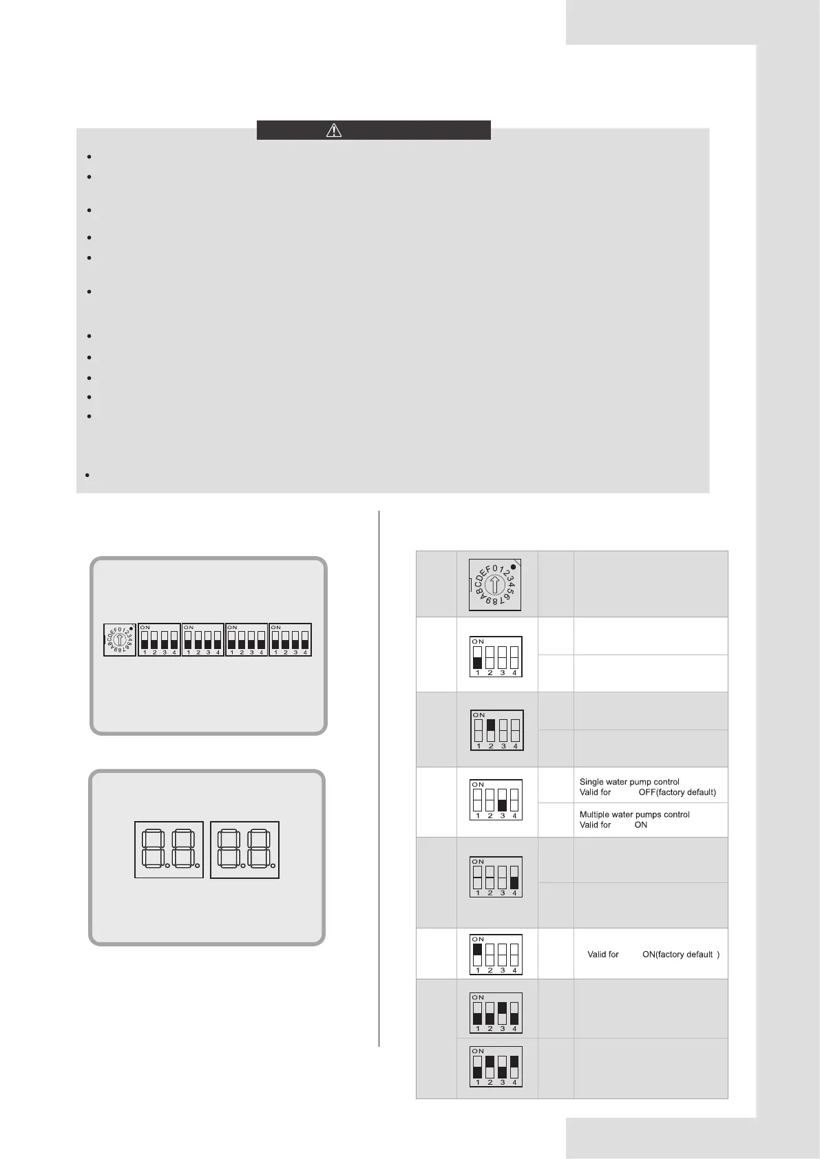
DIP switch, buttons and digital display positions of uints.
Fig. 8-7 Display positions
8.4.3 DIP switch instructions
Table 8-4 65KW and 110KW
ENC1
S1 S2 S3 S4
ENC1
0-F valid for uint address setting
on the DIP switches
0 indicates the master unit and 1-F
the auxiliary uints
(parallel connection) (0 by default)
0-F
OFF
ON
Normal control
Valid for S1-1 OFF(factory default)
Remote control
valid for S1-1 ON
S3-1
OFF
ON
S4
0010
0101
ON
S1-3
S1-4
S1-1
DIP switch for capacity selection
(65KW defaults 0010)
DIP switch for capacity selection
(110KW defaults 0101)
S1-3
S3-1
S1-3
OFF
ON
Normal outlet water temperature
Valid for S1-2 OFF
High outlet water temperature
valid for S1-2 ON(factory default)
OFF
ON
Single variable frequency pump
control of unit valid for S1-4 OFF
(factory default)
Frequency conversion pump plus
constant frequency pump control
of unit valid for S1-4 ON.
S1-2
 Loading...