Do you have a question about the Midea UR-PC160E-DQ and is the answer not in the manual?
Provides essential safety instructions for operating the appliance, covering general precautions and electrical safety.
Details safety guidelines related to refrigerant handling, emphasizing explosion hazards and proper servicing procedures.
Instructions on how to safely move and place the refrigerator, including waiting time before power-on.
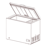
Guidance on dismantling and reassembling the refrigerator door, if needed for room access.
Recommendations for choosing an installation location that ensures proper ventilation for heat dissipation and energy efficiency.
Steps to adjust the refrigerator's footing to ensure it is placed steadily and level.
Instructions for reversing the door swing direction, if required for installation.
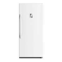
Details on how to install the handle onto the refrigerator door.
Instructions for installing an optional door lock mechanism.
Guidance on adjusting the door to ensure it hangs level and seals properly.
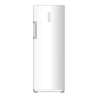
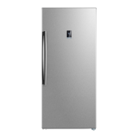
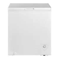
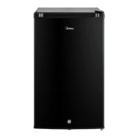
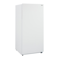
Defines the specific model designation for the refrigerator.
Indicates where to find the product's nameplate, containing essential identification information.
Specifies the type or category of the refrigerator model.
Details the electrical characteristics, including voltage, current, and component specifications.
Defines the acceptable temperature range and tolerance within the refrigerator compartments.
Lists the components involved in the automatic defrosting system.
Presents the electrical schematic diagram of the refrigerator's main components and connections.
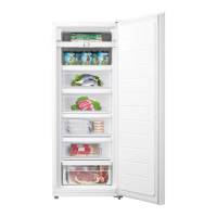
Identifies and labels the key internal components of the refrigerator.
Provides the external dimensions of the refrigerator for installation planning.
Illustrates the flow path of the refrigerant through the system's components.
Shows the path of air circulation within the refrigerator for cooling.
Instructions for removing the door seal from the refrigerator door.
Guides for dismantling internal components such as shelves, CO2 can mounts, and beer can pads.
Information regarding the internal lighting system, if applicable.
Details on dismantling the air duct components and fan motor in the refrigerating chamber.
Procedures for dismantling air duct components and fan motor in the freezing chamber.
Covers the evaporator, defrost thermostat, fuse, defrost sensor, and defrost heater.
Instructions for accessing and dismantling the compressor case and rear cover.
Procedures for removing the temperature control board mounting box and its screws.
Procedures for removing screws and the main control panel cover.
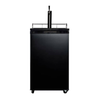
Procedures for disassembly and installation related to the bar counter and its door seal.
Details on the disassembly and installation of the water valve and water tank components.
Instructions for disassembly and installation of the ice maker, water system, and sensor.
Overview of the operation panel, including display icons and control keys.
Instructions on setting and adjusting the refrigerator's temperature, and switching between Celsius/Fahrenheit.
Information regarding alarm functions and indicators.
Lists error codes and provides step-by-step solutions for common faults.
Explanation of how the automatic defrosting process works, triggered by sensor readings.
Details on the control mechanism for the compressor fan.
Information on the self-diagnosis features of the refrigerator.
Description of the power supply circuit, including voltage conversion and filtering.
Details regarding the circuit used for door trip testing.
Explanation of the temperature sensing circuit, NTC thermostat characteristics, and testing methods.
Description of the circuit for the fan motor in the freezing chamber.
Details the circuit diagram for the refrigerator's fan motor and troubleshooting steps.
Description of the circuit for the condensing fan motor.
Details on the circuit controlling the damper motor.
Provides a table of resistance values for temperature sensors at various temperatures.
A flowchart guiding users through diagnosing and resolving 'no cooling' issues.
A flowchart for troubleshooting the 'compressor not working' problem.
A flowchart to diagnose and resolve issues related to internal frosting and lack of defrosting.
Troubleshooting steps for issues where the interior lights of the refrigerator are not functioning.
Guidance on diagnosing and resolving problems with the air duct system not operating correctly.
Steps to identify and fix issues related to fan failure within the refrigerator.
Troubleshooting procedures for a malfunctioning defrost circuit.
A flowchart and explanations for diagnosing and resolving various types of noise issues.
References to figures detailing various parts of the refrigerator.
Provides a list of all replaceable parts and components for the appliance.
References to detailed electrical schematic diagrams for service purposes.
Lists necessary tooling, equipment, and materials required for refrigerator maintenance and repair.