This document serves as a Technical Service Guide for the Midea WQP6-3209 Compact Dishwasher, a 6-setting model designed for efficient dishwashing. It provides comprehensive information for individuals with adequate electrical, electronic, and mechanical experience to safely and effectively service the appliance.
Function Description
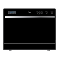
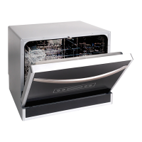
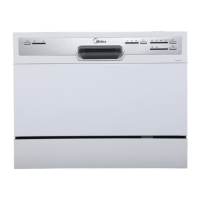
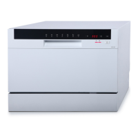
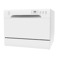
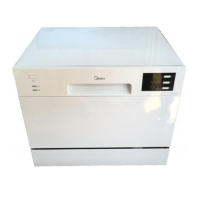
The Midea WQP6-3209 is a compact electrical dishwasher featuring three distinct washing cycles to cater to various cleaning needs. Its primary function is to automatically wash and clean dishes, offering a convenient and effective solution for household dishwashing. The dishwasher incorporates electronic controls, making operation straightforward and user-friendly. It is designed to accommodate up to six place settings, making it suitable for smaller households or as a secondary dishwasher. The appliance's compact dimensions allow for flexible placement within a kitchen, with a recommendation to position it where water hose connections are easily accessible.
At the heart of the dishwasher's operation is the Main control board, which governs all electrical elements. This board is housed within a protective box at the bottom of the dishwasher and is designed for easy replacement should it malfunction. The control board receives signals from various sensors and switches to manage the washing cycles, water intake, heating, and draining processes.
Water intake is regulated by the Inlet valve, which is controlled by the main control board based on signals from the Flowmeter. The flowmeter monitors and measures the rate of water flow into the dishwasher, ensuring the correct amount of water is supplied for each cycle. Once water fills the basin, the Pressure switch detects the air pressure increase in its hose. When the pressure reaches a predetermined value, the switch signals the main control board, which then initiates the drain pump.
The dishwasher's cleaning action is facilitated by a Sprayer system, which distributes water and detergent throughout the wash chamber. Detergent and rinse aid are dispensed automatically by the Dispenser at appropriate times during the wash cycle. The dispenser is activated twice: first, to release detergent, and second, to release rinse aid. A Magnetic sensor within the dispenser is linked to the rinse aid warning light on the control panel, indicating when a refill is needed.
Heating elements, specifically the Heater elements assembly, are responsible for heating the water to the required temperature for effective cleaning. A Thermal resistor monitors the water temperature, providing feedback to the main control board to maintain optimal heating. The Drain pump assembly is crucial for removing wastewater from the dishwasher after each wash phase. The Motor pump assembly drives the water circulation during the wash cycles.
For areas with hard water, the dishwasher may include a Water softener to improve washing performance by conditioning the water. The Floater assembly and its associated Microswitch (floater assembly) act as a safety mechanism, detecting excessive water levels and preventing overflows.
The Door Handle Assembly and its integrated Microswitch (door handle assembly) play a critical role in the dishwasher's operation. This microswitch connects a forceful electric power to all loads of the dishwasher in series. When the microswitch closes, the dishwasher machine is stopped, ensuring safety by preventing operation when the door is open.
Usage Features
The WQP6-3209 dishwasher is designed for ease of use, with a straightforward control panel.
- Power ON/OFF Button: This button allows users to turn the dishwasher's power supply on or off. A "Power on light" illuminates when the button is pressed, indicating that the unit is active.
- Washing Program Selector: A rotary knob enables users to select from the available wash cycles, providing flexibility for different cleaning needs.
- Start/Reset Button: This button initiates or pauses the selected wash program.
- Running Indicator Light: During operation, a corresponding light on the control panel displays the current status. If the machine is paused, this light will flicker.
- Rinse Aid Warning Light: This indicator illuminates when the rinse aid dispenser requires refilling, prompting the user to add more rinse aid for optimal drying performance.
- Salt Warning Light: For models equipped with a water softener, this light indicates when the softener needs to be refilled with salt.
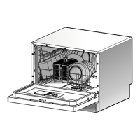
The dishwasher's interior is designed for practical use, featuring a cutlery basket and a main basket to organize dishes and utensils. A Filter System is integrated to trap food particles, preventing them from recirculating and ensuring cleaner dishes.
Maintenance Features
The service guide provides detailed instructions for the removal and replacement of various components, facilitating maintenance and repair. Safety is paramount, with warnings to always disconnect power before servicing and to ensure all grounding devices are reconnected properly after repairs.
Main Control Board: Replacement involves disconnecting power, removing the cutlery basket, main basket, and filter system, then turning the dishwasher to access and remove the protective box cover. All housings and terminals must be carefully pulled out, noting their positions and colors, before unscrewing and removing the board.
Outer Door: Servicing the outer door requires opening the dishwasher, removing screws that fix the outer door assembly, and then removing screws for the operating board.
Dispenser: To access the dispenser, the outer door assembly must be removed. All dispenser terminals are then pulled out, and screws fixing the dispenser are removed.
Door Handle Assembly & Microswitch: Disconnecting power and removing the outer door assembly are initial steps. The snap-fits fixing the microswitch are unfitted, and the microswitch is pulled out. Terminals of the microswitch should not be pulled out during this process.
Inner Door: After removing the outer door assembly, terminals of the dispenser and microswitch (including locking terminals) are pulled out, and screws fixing the inner door are removed.
Shell: This involves removing the cutlery basket, main basket, and filter system. Screws fixing the shell to the tank assembly, backboard, and bottom board are removed. The dishwasher is then turned to access screws fixing the shell to the bottom board. Various snap-fits connecting the shell to other parts must also be unfitted.
Operating Board: Disconnecting power, removing the shell, corner boards, absorber sound, backboard, and hollow plate are necessary. Screws for the protective box cover are removed, and housings and connecting lines for the operating board are pulled out.
Air Breather Assembly: After removing the shell and associated panels, the nut of the air breather is contrarotated, and the gasket and clamp for the connecting hose are removed.
Siphon: Similar to the air breather, shell and panel removal precedes contrarotating the nut of the siphon, taking out the one-way valve and gasket, and removing clamps for connecting hoses.
Pressure Switch: Shell and panel removal are required. The sheet copper fixing the pressure switch hose is unfixed, and the snap-fit of the bottom board for fixing the pressure switch is unfitted. The pressure switch hose and all terminals are then pulled out.
Tank Assembly: This extensive procedure involves removing the cutlery basket, main basket, filter system, shell, corner boards, absorber sound, backboard, hollow plate, and screws for the protective box cover. Housings and connecting lines for the operating board are pulled out, and the outer door assembly is removed. Terminals for the microswitch, dispenser, and rod for door hinges are disconnected. The plug terminal of the tank assembly, including its screw and nut for ground lines, is removed. The sheet copper for the pressure switch hose is unfixed, and screws for the spray holder are removed. The cover of the water softener, nuts of the air breather, siphon, and sump assembly are contrarotated. Door springs and connecting lines are taken out, and all screws for the front chamber brackets are removed, along with unfitting snap-fits of the bottom board.
Sump Assembly: This involves removing the cutlery basket, main basket, filter system, shell, corner boards, absorber sound, backboard, hollow plate, and tank assembly. All terminals and housings of the sump assembly, including those for the drain pump, motor pump, heater elements, and thermal resistor, are pulled out. Clamps for connecting hoses are removed, and the hose for the water softener and pressure switch hose are pulled out. The sump assembly is then pulled from the motor vibration-proof pad.
Drain Pump Assembly: The sump assembly must be removed first, followed by unscrewing and contrarotating the drain pump assembly.
Motor Pump Assembly: After removing the sump assembly, all screws fixing the sump pump assembly are removed.
Heater Elements Assembly: The sump assembly is removed, then all screws fixing the heater elements assembly are removed, along with the heater elements support assembly, nuts, and gaskets.
Heater Elements Support Assembly: This requires removing the sump assembly and heater elements assembly, then taking out the gasket.
Thermal Resistor: After removing the sump assembly, it is turned, and all screws for fixing the thermal resistor are removed.
Check Plate: The sump assembly is removed, and the check plate holder assembly is pulled out. The check plate is then pulled from its holder.
Flowmeter: This involves removing the cutlery basket, main basket, filter system, shell, corner boards, absorber sound, backboard, hollow plate, and tank assembly. The plug housing for the male terminal is removed, and all clamps for fixing the connecting hose are detached.
Inlet Valve: Similar to the flowmeter, removal of the cutlery basket, main basket, filter system, shell, corner boards, absorber sound, backboard, hollow plate, and tank assembly is required. Two locking terminals for the inlet valve are removed, followed by the inlet valve block and the inlet valve itself, along with the clamp for its connecting hose.
Floater Assembly & Microswitch (floater assembly): This involves removing the cutlery basket, main basket, filter system, shell, corner boards, absorber sound, backboard, hollow plate, and tank assembly. The bottom board is lifted to remove screws for the floater assembly. All locking terminals for the microswitch are pulled out, and one screw fixing the microswitch is removed.
Water Softener: For models equipped with a water softener, removal involves the cutlery basket, main basket, filter system, shell, corner boards, absorber sound, backboard, hollow plate, and tank assembly. The air breather and its O-rings are pulled out, followed by the gasket of the water softener and the connecting hose. All terminals for the water softener are then pulled out.
The guide also includes a detailed troubleshooting section, linking common symptoms to potential causes and providing corresponding remedies. This allows for efficient diagnosis and repair of issues such as water not filling, pump malfunctions, heating problems, door closure issues, and water leaks.