This document provides a technical service guide for the Midea Compact Dishwasher, model series WQP6-3705, offering insights into its function, technical specifications, usage, and maintenance.
The dishwasher is designed to efficiently clean dishes with 6 washing cycles, ensuring high performance and meeting various washing requirements. Its electronic control system is user-friendly and convenient to operate. The rack system is versatile, allowing for 6 sets of dishes, and can be adjusted in height (550mm x 438mm x 500mm) to accommodate different kitchen layouts, with a recommended water hose connection.
Important Safety Notice:
The manual emphasizes that the information provided is intended for use by individuals possessing adequate backgrounds in electrical, electronic, and mechanical experience. Any attempts to repair a major appliance may result in personal injury and property damage. The manufacturer or seller is not responsible for the interpretation of this information, nor can it assume any liability in connection with its use.
Warning:
To avoid personal injury, disconnect power before servicing the product. If electrical power is required for diagnosis or test purposes, disconnect the power immediately after performing the necessary checks.
Reconnect All Grounding Devices:
If grounding wires, screws, straps, clips, nuts, or washers used to complete a path to ground are removed for service, they must be returned to their original position and properly fastened.
Technical Specifications:
- Rated voltage: 220-240V / 50Hz
- Rated power: 1170-1380W
- Water pressure: 0.04-1.0MPa
- Water temperature: maximum 60°C
- Capacity: 6 settings
Control Panel Features:
The control panel includes several buttons and indicators for operation:
- Power Button (1): To turn on/off the power supply.
- Program Indicator (2): Displays the selected washing program.
- Delay Button (3): Used to press the button to delay the start of a cycle.
- Display Screen (4): Shows the remaining time and the state (running status, delay time, etc.).
- Rinse Aid Warning Light (5): To be on when the rinse aid dispenser needs to be refilled.
- Faucet Light (6): To be on when the faucet is opened.
- Program Indicator (7): Displays the selected program, which can include:
- Intensive
- Heavy
- ECO
- Glass
- 90Min
- Rapid
- Program Button (8): To press the button to choose the program.
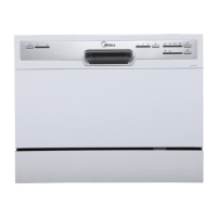
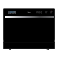
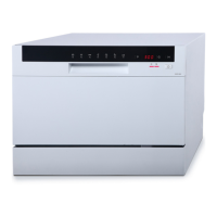
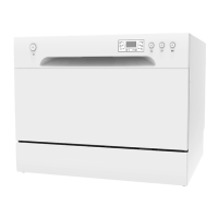
Note: All models have different control panel features and appearances. All details are to be referred to user manuals of the model.
Component Locator Views:
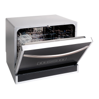
Front View (Outer Door):
The front view shows the outer door (1).
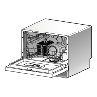
Interior View (with basket):
Inside the dishwasher, key components include:
- Cutlery basket (1)
- Basket (2)
- Dispenser (3)
- Inner door (4)
Interior View (With Basket Removed):
With the basket removed, additional internal components are visible:
- Nut of air breaker (1)
- Water Softener cover (2)
- Sprayer (3)
- Filter System (4)
Back View:
The back view reveals external connections:
- Bottom board (1)
- Power cord (2)
- Inlet hose connecter (3)
- Outer drain hose (4)
Dishwasher Components - Maintenance Features:
The manual provides detailed instructions for the removal and replacement of various components, emphasizing safety and proper connection.
Main Control Board:
The main control board controls all electrical elements in the dishwasher machine. It is located in the protecting box in the bottom of the dishwasher machine. It is easy to replace when it cannot work.
- Removal and Replacement:
- Disconnect power supply.
- Take off cutlery basket, basket, and filter system.
- Turn the dishwasher machine, and unfix all snaps for fixing cover of bottom board.
- Pull out all housings and terminals (including some locking terminals), then unfix all snaps for fixing main control board.
- Reverse the above procedure to install. And check out all connectors connected well.
- Part Name: 1 – cover of bottom board, 1 – protecting box, 2 – main control board.
- Note: Mark all housings and terminals' positions and colors before pulling out them. Some terminals are locking terminals.
Floater Assembly:
- Part Name: 1 – cover of bottom board, 2 – microswitch, 3 – floater holder, 4 – floater.
- Removal and Replacement:
- Remove cover of bottom board (see main control board removal and replacement).
- Pull out all terminals of microswitch.
- Unfit snaps fixing microswitch to floater holder.
- Unfit snaps fixing floater holder to cover of bottom board.
- Reverse the above procedure to install. And check out all connectors connected well.
Heating Pump Motor Assembly:
- Part Name: 1 – heating pump assembly, 2 – lower pump cover, 3 – motor assembly, 4 – motor hanger.
- Removal and Replacement:
- Remove cover of bottom board (see main control board removal and replacement).
- Pull out all terminals of heating pump motor assembly.
- Remove clamps fixing heating pump motor assembly to sump of bottom board.
- Unfit motor hangers fixing heating pump motor assembly to bottom board.
- Reverse the above procedure to install. And check out all connectors connected well.
Motor Assembly:
- Part Name: 1 – upper pump cover, 2 – heating element, 3 – pressure switch assembly.
- Removal and Replacement:
- Take out heating pump motor assembly from the dishwasher machine (see main heating pump motor assembly removal and replacement).
- Unfit snap of heating pump assembly, and contrarotate heating pump assembly.
- Reverse the above procedure to install. And check out all connectors connected well.
Drain Pump Assembly:
- Part Name: 1 – motor hanger, 2 – impeller assembly, 3 – pump seal ring, 4 – lower pump, 5 – motor assembly.
- Removal and Replacement:
- Take out heating pump motor assembly from the dishwasher machine (see main heating pump motor assembly removal and replacement).
- Disassemble heating pump motor assembly (see heating pump assembly removal and replacement).
- Take out two motor hangers, and remove screws for fixing impeller assembly and lower pump to motor assembly.
- Reverse the above procedure to install. And check out all connectors connected well.
Check Plate:
- Part Name: 1 – inner drain hose, 2 – check plate assembly.
- Removal and Replacement:
- Remove cover of bottom board (see main control board removal and replacement).
- Remove clamp fixing inner drain hose to bottom board, and pull it out.
- Pull out check plate from check plate holder, and replace a new check plate.
- Reverse the above procedure to install. And check out all connectors connected well.
Inlet Valve:
- Removal and Replacement:
- Remove cover of bottom board (see main control board removal and replacement).
- Pull out all terminals of inlet valve.
- Remove clamp for fixing connecting hose to inlet valve, and contrarotate inlet valve to take it out.
- Reverse the above procedure to install. And check out all connectors connected well.
Control Panel:
The outer door covers the door to the dishwasher and protects the detergent dispenser.
- Part Name: 1 – Control panel, 2 – operating board.
- Removal and Installation:
- Open the door of dishwasher. And remove all screws for fixing control panel.
- Remove screw, and unfix all snaps for fixing the pcb cover, then take out operating board.
- Reverse the above procedure to install. And check out all connectors connected well.
Operating Board:
- Removal and Replacement:
- Disconnect power supply.
- Remove all screws for fixing control panel (see control panel removal and installation).
- Pull out all housings for connecting operating board.
- Remove screw and unfix all snaps for fixing the operating board (see control panel removal and installation).
- Reverse the above procedure to install. And check out all connectors connected well.
Outer Door:
The outer door covers the door to the dishwasher and protects the detergent dispenser.
- Removal and Installation:
- Open the door of dishwasher. And remove all screws for fixing outer door.
- Reverse the above procedure to install. And check out all connectors connected well.
- Front View (with outer door assembly removed):
- Part Name: 1 – stream resistant cotton, 2 – dispenser, 3 – sound absorbing cotton, 4 – door hinge (left), 5 – door hinge (right), 6 – rod for door hinges, 7 – kick board.
Dispenser:
The dispenser automatically dispenses both the detergent and the rinse agent at the appropriate times. The dispenser is activated twice during a wash cycle.
The first time, the dispenser is activated, the lever slides up the right-hand path of the connecting rod. This action moves the cover catch and releases the detergent cover. When deactivated, the lever resets to rest under the notch in the center of the connecting rod. When activated for the second time in a cycle, the lever hits the connecting rod by the notch, lifting the rinse dispenser plunger and releasing the rinse agent. When deactivated, the lever returns to its original starting position. The magnetic sensor is connected to rinse aid warning light at control panel by wires. When the indicator lights up, it should add more rinse aid.
- Part Name: 1 – cover catch, 2 – detergent power compartment, 3 – cover, 4 – sight glass, 5 – rinse agent cap, 6 – detergent tablet compartment.
- Part Name: 1 – electromagnetic valve, 2 – lever, 3 – plunger, 4 – connecting rod, 5 – magnetic sensor.
- Removal and Replacement:
- Remove outer door assembly (see outer door removal and installation).
- Pull out all terminals of dispenser. Then remove all screws for fixing dispenser.
- Reverse the above procedure to install. And check out all connectors connected well.
- Part Name: 1 – dispenser brackets, 2 – dispenser.
Inner Door:
- Caution: Inner door of edges are sharp.
- Removal and Replacement:
- Remove outer door assembly (see outer door removal and installation).
- Remove control panel (see control panel removal and installation).
- Remove dispenser (see dispenser removal and replacement).
- Remove all screws for fixing inner door to right hinge assembly and left hinge assembly.
- Remove dispenser (see dispenser removal and replacement).
- Reverse the above procedure to install. And check out all connectors connected well.
Shell:
- Removal and Installation:
- Remove all screws for fixing shell with tank and bottom board assembly in the rear of dishwasher machine.
- Push the shell from front to back. And take it away from the machine.
- Reverse the above procedure to install. And check out all connectors connected well.
Door Lock Assembly:
- Part Name: 1 – door switch assembly, 2 – absorber, 3 – backboard.
- Removal and Replacement:
- Disconnect power supply.
- Remove shell (see shell removal and installation).
- Unfit snap of door lock assembly, and push it out.
- Pull out all terminals of microswitch fixed on the door lock assembly.
- Reverse the above procedure to install. And check out all connectors connected well.
Air Breaker:
- Removal and Replacement:
- Remove shell (see shell removal and installation).
- Take out absorbing cotton, upper basket and lower basket.
- Contrarotate nut of air breaker and take it out.
- Pull out terminal of air breaker, and unfit snaps of air breaker fixing on softener.
- Turn the dishwasher machine, remove the cover of bottom board (see main control board removal and installation).
- Remove all clamps for fixing connecting hoses to air breaker.
- Reverse the above procedure to install. And check out all connectors connected well.
Hinge Assembly and Spring System:
- Part Name: 1 – spring holder, 2 – spring, 3 – friction strip, 4 – absorbing cotton, 5 – hinge assembly.
- Removal and Replacement:
- Remove shell (see shell removal and installation).
- Take out absorbing cotton.
- Take off spring holder from the slot of bottom board.
- Caution: This operation must be more carefully, it is easy to be injured by the friction strip.
4. Remove all screws for fixing hinge assembly to bottom board.
5. Reverse the above procedure to install. And check out all connectors connected well.
Tank Assembly:
- Removal and Installation:
- Remove shell (see shell removal and installation).
- Take out absorbing cotton.
- Remove air breaker (see air breaker removal and replacement).
- Remove all screws for fixing tank assembly to bottom board.
- Reverse the above procedure to install. And check out all connectors connected well.
Test Program:
The test program is designed to check the operation of components and identify malfunctions, intended for technicians.
How to activate Test Program:
To activate the test program, with the door opened and within 60s after power on, hold down the Program button and press the POWER button until the machine enters Test Program. Then close the door to start the Test Program.
During test program running, you can press the Program button to jump into the next step (except the inlet valve step).
Test Program Operation:
- How to activate: With door opened, Program + Power.
- Start Test Program: Close the door.
- Jump into next step: Program.
- Error Codes: E1, E3, E4, E6, E7.
Procedure of Test Program (for models controlling water filling by flowmeter):
- 0 (8:88): Initialization - Power on, stand by.
- 1 (05 or Turbidity value): Inlet Valve - Open inlet valve and feeds with 1.9L water. Running fan closed after 10 seconds.
- 2 (04/Temperature value): Washing Pump and Heating Element - Run washing pump and 10s later run heating element until the water temperature reaches 57°C. Then the machine will pause. Press Program button to jump into the next step.
- 3 (03): Washing Pump and Dispenser - Washing pump for 10s, dispenser will act for 45s in this step.
- 4 (02): Static - Static 30s.
- 5 (01): Drain Pump - Drain for 30s.
- 6 (F):* Finish - Buzz one sound, stop, and stand by.
Troubleshooting - How does the appliance react when error code occurred:
E1 Water filling exceed pre-set time:
If the inlet valve has been opened for 4 minutes but the water quantity hasn't reached the desired value (measured by pulses), E1 would occur. When E1 occurs, the drain pump will run until the flowmeter keeps motionless for 2 minutes, and all other components will be stopped immediately. At the same time, the buzzer will alarm for 30 seconds, and error 1 will be shown.
E3 Heating exceed pre-set time:
If the heating element has been working for 60 minutes but the water temperature detected by NTC hasn't reached the desired value, E3 would occur. When E3 occurs, the drain pump will run until the flowmeter keeps motionless for 2 minutes, and all other components will be stopped immediately. At the same time, the buzzer will alarm for 30 seconds, and error 3 will be shown.
E4 Overflow:
At any time, if the overflow micro-switch acts and keeps for longer than 2 seconds, E4 would occur. When E4 occurs, the drain pump will run until the flowmeter keeps motionless for 2 minutes, and all other components will be stopped immediately. At the same time, the buzzer will alarm for 30 seconds, and error 4 will be shown.
- Note: Priority level of E4 is the highest. E4 operation is valid after other error operations have been done. When E4 operation has been done, all the others are invalid.
E6 Open-circuit failure of thermistor:
In the test program, once an open-circuit failure of the thermistor is detected by the controller, E6 would occur. When E6 occurs, the drain pump will run until the flowmeter keeps motionless for 2 minutes, and all other components will be stopped immediately. At the same time, the buzzer will alarm for 30 seconds, and error 6 will be shown.
E7 Short-circuit failure of thermistor:
In the test program, once a short-circuit failure of the thermistor is detected by the controller, E7 would occur. When E7 occurs, the drain pump will run until the flowmeter keeps motionless for 2 minutes, and all other components will be stopped immediately. At the same time, the buzzer will alarm for 30 seconds, and error 7 will be shown.
Troubleshooting Trees (E1, E3, E4, E6-E7):
The manual provides detailed flowcharts for diagnosing and resolving issues related to each error code. These trees guide the technician through a series of checks and actions, including:
- E1 Tree (Longer inlet time): Checks for water in the tub, inlet hose condition (kinked/blocked), inlet valve circuit, and flowmeter circuit. Actions include replacing parts, reconnecting wires, or giving advice to the consumer.
- E3 Tree (Longer heating time): Checks water temperature, filter jamming, heater circuit, washing pump circuit, and NTC circuit. Actions include replacing switches, clearing filters, reconnecting wires, or replacing parts.
- E4 Tree (Overflow): Checks for water on the bottom board, flooding switch circuit, drain hose condition, and flowmeter circuit. Actions include reconnecting wires, repairing/replacing parts, or giving advice.
- Do as follows (for E4): Remove the shell, remove water from the bottom board, restart with a strong/standard wash program, observe the bottom tray, and check for leaks from various components.
- E6-E7 Tree (Open/Short-circuit failure of thermistor): Checks the NTC circuit and flowmeter circuit. Actions include reconnecting wires or replacing the NTC.
Final Troubleshooting Note:
If the problem has not been solved through all the inspections mentioned above, the PCB may have a malfunction. In such cases, replace the PCB and test again.
Caution:
Because the real situation is unpredictable, inspection trees mentioned in this manual are for reference only.