GR8-1250 WALMART
Midtronics Inc. 7000 Monroe Street Willowbrook, IL 60527
www.midtronics.com
12
Chapter 2: Overview
Chapter 2: Overview
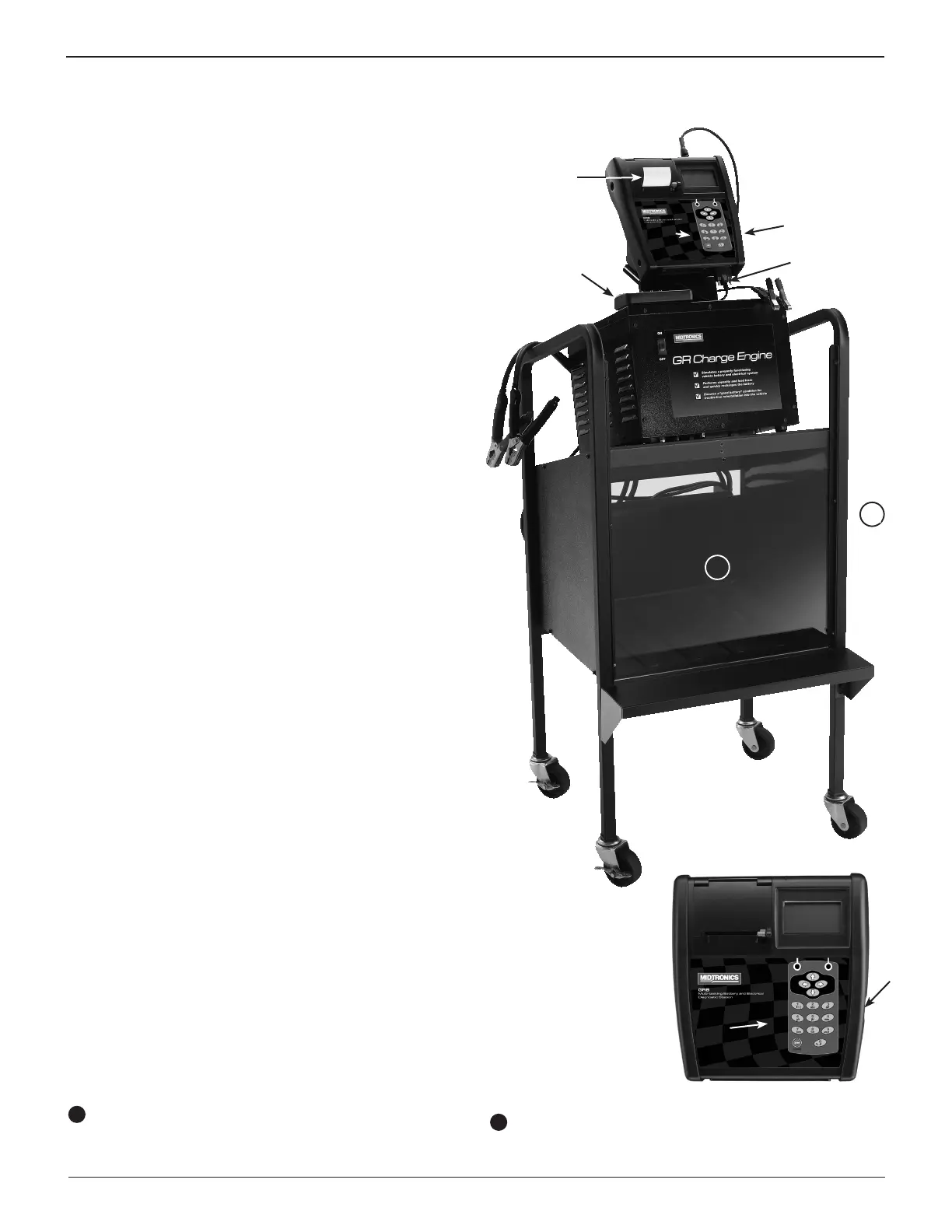
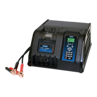
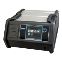
Battery Diagnostic Station: Front View
The controls to the Battery Diagnostic Station are accessible
on the front of the Control Module and the GR Charge Engine.
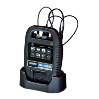
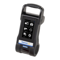
Control Module
Backlit graphical display and keypad for data entry. Provides
battery analysis and controls the charge session.
Integrated Printer
Thermal printer prints test results in either English, French-
Canadian, or Spanish
Data Card Slot
For future upgrades via an data card. The slot contains a
plastic ller card for protection.
Status Light
Lights in conjunction with beeping alarm to indicate
transitions and warnings.
Serial Cable Connection: Control Module
The short serial cable connects the Control Module to the
Multitask Bridge.
Multitask Bridge
Allows the unit to charge one battery while testing another.
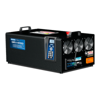
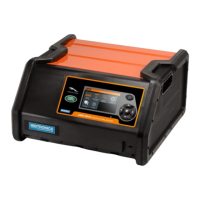
GR Charge Engine
Provides charge current when needed, which is regulated
by the Control Module.
ON/OFF Switch
Turns power on and o to the Battery Diagnostic Station.
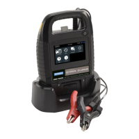
Diagnostic Charger Cables and Clamps
Feed the cables into the Battery Charging Compartment
though the slot in rear of the cart before connecting the
clamps to the battery posts. For long term storage, place
the cables in the empty compartment.
Battery Test Cables
These cables are used for testing only. No charging is
possible with these cables.
11
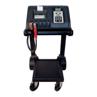
Battery Charging Compartment (Cart Optional)
Enclosed area for safely charging a battery.
12
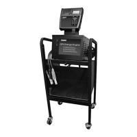
Charge Engine Cart (Optional)
11
12