31
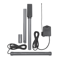
Operator
Fence Post
Gate Post and Gate Cross Member
(In Closed Position)
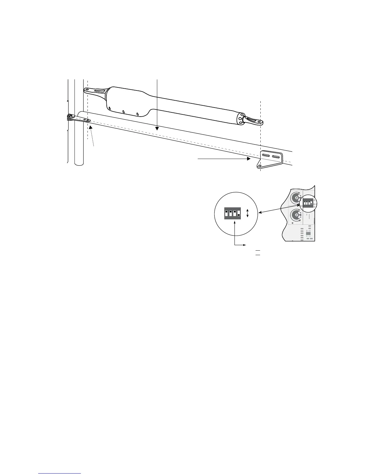
POST PIVOT BRACKET level with the
horizontal surface of the GATE BRACKET
LEVEL
LEVEL
LEVEL
Step 3
With the gate in the fully closed position and the opener retracted, swing the opener to the gate. Mark reference points for
bolt holes on gate cross member through middle of gate bracket slots. The opener must be level. (Some vertical adjustment
is possible by sliding the post bracket assembly up and down.) Drill
3
/8" holes into the gate cross member as marked. Fasten
gate bracket to cross member using (2) 3/8" x 3" bolts, washers, lock washers, and nuts. Attach the opener to the post bracket
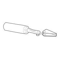
assembly and gate bracket using clevis pins, bushings, and hairpins clips.
Step 4
Make sure the control box power switch is OFF. Use a small
screwdriver to move the Number 3 DIP switch from the factory
setting (OFF / Pull-To-Open) to ON for Push-To-Open. Turn
power switch ON.Thecontrolboardisnowconguredtopush
the gate open.
Setting the Open Position Limit
Step 1
ConrmthatthepowerswitchisintheONposition,andthegatesareintheCLOSEDPOSITIONS.
Step 2
Activate your openers by pressing the entry transmitter button. Your gates should now be moving from the closed positions
towardtheiropenposition.PreparetoSTOPgatesbypressingtheentrytransmitterbuttonagainwhentherstgatereaches
the desired open position. This step may be repeated until desired open position is achieved. Once the desired OPEN
position has been achieved, proceed to step 3.
Step 5
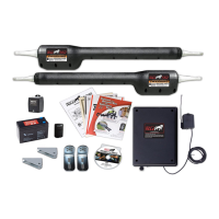
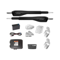
Install the second gate opener on the other gate in the same manner.
Then refer to the CONTROL BOARD SETTINGS on page 25 for
gate sequencing and other programming steps before proceeding.
DIP#3
ON Push-to-open operation.
OFF Pull-to-open operation (factory setting).
ON
OFF
1
ON DIP
234
1 2 3 4
ON
OFF
SOFT START OFF
WARNING OFF
OPEN PULL
SLV OPEN DLY.
MODE1 OFF
ON
ON
PUSH
SIMULT.
ON
120 MIN MAX
AUTO CLOSE TIME STALL FORCE
1 2 3 4
ON DIP
OFF
OFF
PULL
DLY.
OFF
OFF
ON
ON
PUS
SIMU
ON
ON
120 MIN
 Loading...