19
Step 2
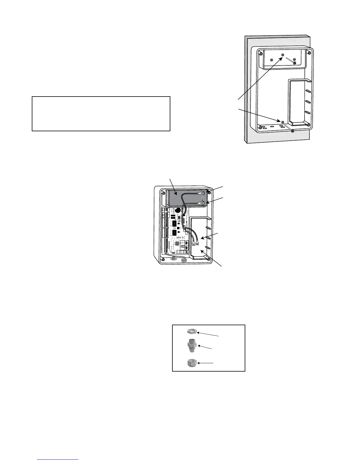
Make sure the control box power switch is
in the OFF position. The ON/OFF Switch
is located on the bottom of the control box.
Remove the control box cover and slide the
battery into position with its terminals to
the RIGHT (see illustration). Connect the
BLACK battery wire to the NEGATIVE
(–) battery terminal. Connect the RED
battery wire to the POSITIVE (+) terminal.
Pay close attention to the color of the wires.
If the wires are connected incorrectly, the
control board will be damaged. NEVER
insert the battery with the terminals to
the left.
Mounting the Control Box
Step 3
Strip approximately
3
/16" of insulation from each
wire of the power cable. Twist each exposed wire
tightly (there are seven [7] wires inside the power cable
sheath). Loosen sealing nut on strain relief hub at
bottom of control box. Insert power cable into control
box through strain relief. Thread approximately 6"
of the power cable into the control box and re-tighten
sealing nut until the power cable locks into place.
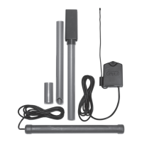
Step 1
Mount the control box using the screws (provided) or another
secure mounting method. The control box must be mounted at
least 3 feet above the ground to protect it from rain splash,
snow, etc., and at least 3 feet from an AC power source to
prevent electrical interference.
25
FUSE
BAT T+
BAT T-
1 2 3 4
ON DIP
STATUS
LEARN RMT
RECEIVER
LEARN
MAST LIMIT
LEARN
SLV LIMIT
S3
S4
ALM
S2
OFF
SOFT START OFF
WARNING OFF
OPEN PULL
SLV OPEN DLY.
MODE1 OFF
MODE2 OFF
ON
ON
PUSH
SIMULT.
ON
ON
120 MIN MAX
CHARGING
PWR IN
GTO RCVR.
WHT
BLU
BRN
ORG
RED
BLK
GRN
WHT
BLU
BRN
ORG
RED
BLK
GRN
COM
GRN
BLK
RED
CYCLE
SAFETY
EXIT
SHADOW
OPEN
EDGE
COM
GTO
TRANSF
LOCK
PWR
AUX
RLY
POWER
INPUTS
CONTROL
OUTPUTS
MASTER CABLESLAVE CABLE
CONTROL INPUTS
AUTO CLOSE TIME STALL FORCE
CLOSE
EDGE
18 VAC
or
SOLAR
GTO
LOCK
AUX
Battery wires for
optional second battery.
BLACK wire to Negative Terminal
RED wire to Posative Terminal
12 Volt Battery
(included)
Space for optional
second 12 Volt battery
(see Accessory Catalog)
Sealing Nut
Hub
Lock Nut
Strain Relief
Use mounting
holes and screws
provided to mount
control box to a
secure surface.
NOTE: The batteries that came with your GTO®
gate opener, MUST be placed in the top (horizontal)
battery slot with the terminals on the RIGHT. The extra
(vertical) battery slot is for the second battery.
 Loading...