Reference Manual
128 MIKE 21 BW - © DHI
define the location of the internal generation line in your model coordinate
system by giving the grid coordinates for the first point and the last point of
the line.
The internal generation line must be parallel to either the x- or y-axis.
Setup of internal generation lines
Using internal generation it is possible to model waves propagating with an
angle to the generation line, and also directional (3D) wave fields.
The positions of the internal generation line(s) and combined sponge layers
are dependent upon the incoming wave conditions - especially the wave
direction and directional spreading.
One generation line
The use of directional waves requires a reasonably wide model area and a
generation line depending on the specified directional distribution. This is
illustrated in Figure 5.14.
The main direction of the waves is perpendicular to the generation line. If the
bound of the directional distribution is +
max
and -
max
, only the area within
the thin red lines will contain all the wave components in the distribution lim-
ited by +
max
and -
max
. Hence, the area of interest should be within this area.
The useful model area is further restricted due to diffraction of waves into the
shadow area outside the thin red lines.
Note, that the directional information on the waves is specified when generat-
ing the input wave files using the MIKE 21 Toolbox tool Random Wave Gen-
eration.
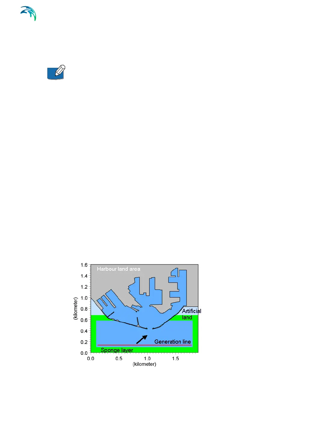
Figure 5.14 Model setup for modelling directional waves