Calibration Parameters
137
made to Schäffer et al (1993) and Madsen et al (1997a). The latter paper is
included in the scientific documentation. Although the breaker model is not
designed for to handle plunging breakers, successful results have been
obtained even with the default breaker parameters listed below.
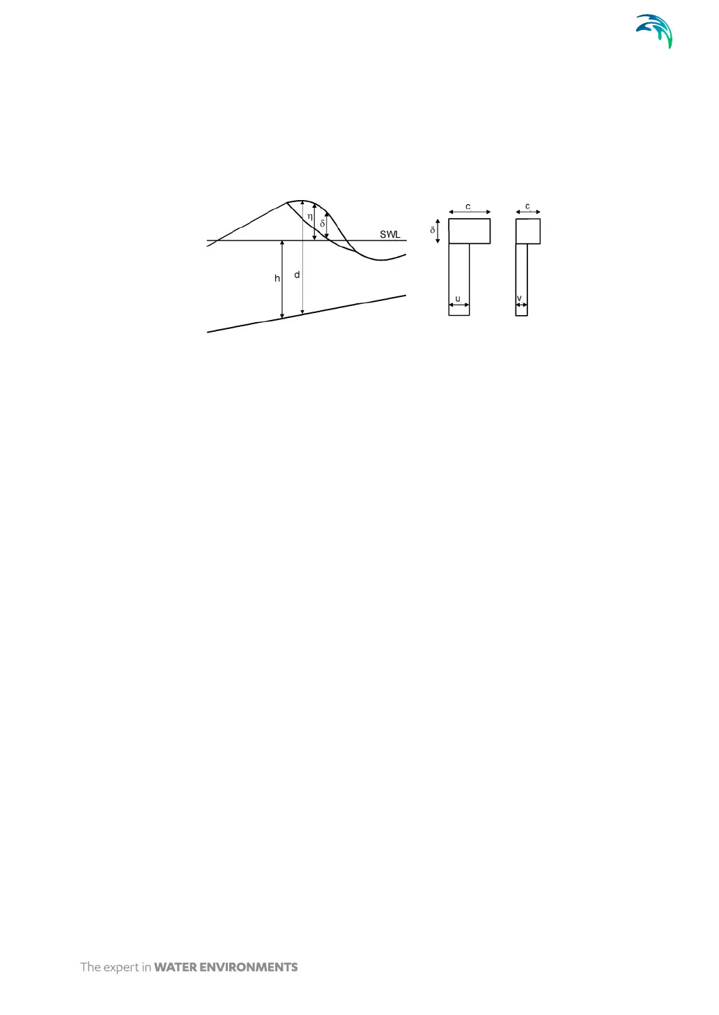
Figure 5.23 Cross-section of a breaking wave and the assumed vertical profile of
the horizontal velocity components
Recommended wave breaking parameters
The surface roller for a breaking wave is calculated using the following
parameters:
Roller form factor
The roller thickness is determined as the water above the tangent of
slope and the resulting thickness is multiplied by a form or shape fac-
tor. The default value is 1.5. For plunging breakers (see section Type
of breakers) Ozanne et al (2000) suggest a value of about 2.0.
Type of roller celerity
The roller celerity is assumed to be proportional to the linear shallow
water celerity. The roller direction can either be determined interac-
tively from the instantaneous wave field (type 1) or set to a prescribed
wave direction (type 3). The first procedure (type 1) may sometime
cause stability problems why the second type is usually recommended.
However, in some applications the wave propagation direction cannot
be set to a characteristic direction as e.g. in the island examples, see
Section 4.2.6.
Roller celerity factor
For the type 1 of roller celerity the default factor is 1.3.
Initial breaking angle
Breaking is predicted to occur when the local slope of the surface ele-
vation exceeds the initial breaking angle. The default value is 20
degrees.