OM-193472 Page 22
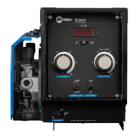
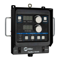
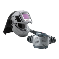
6-2. Optional Side Panel Controls
Ref. 802 357-A / Ref. 186 589 / 210 436-A
1 Preflow Control
Control sets time gas flows before
welding wire is energized. Time
range is 0 to 5 seconds.
2 Postflow Control
Control sets time gas flows after
completion of burnback. Time
range is 0 to 5 seconds.
3 Spot Time Control
Factory set for 0.25 to 5 seconds of
spot time. Rotating knob fully
counterclockwise selects an
untimed continuous weld.
4 Run-In Control
Use control to set wire feed speed
before arc initiation.
Close side door.
3
1
2
4
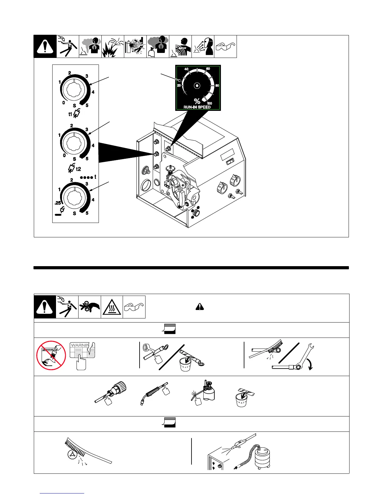
SECTION 7 − MAINTENANCE & TROUBLESHOOTING
7-1. Routine Maintenance
! Disconnect power before maintaining.
3 Months
Replace
Unreadable
Labels
Clean And
Tighten
Weld
Terminals
Repair Or
Replace
Cracked
Weld Cable
14-Pin Cord Gas HoseGun Cable
Replace
Cracked
Parts
6 Months
Blow Out Or Vacuum
Inside,
During Heavy Service,
Clean Monthly
OR
Clean
Drive
Rolls