OWNER’S MANUAL
1999 MILLER Electric Mfg. Co.
OMĆ1035 169 965B
June 1999
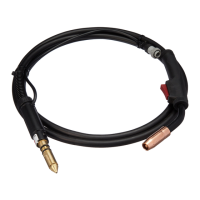
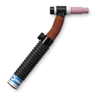
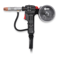
M-10, M-15, M-25, And M-25M Guns
1. Specifications
Air-Cooled Guns For GMAW And FCAW Welding
Note: Using gasless flux cored wire reduces gun duty cycle.
M-10 Feeds .023 To .045 in (0.6 To 1.1 mm) Hard Or Flux Cored Wires
Duty Cycle Rating:
100%: 100 A With CO
2
Shielding Gas
60%: 100 A With Mixed Gases
M-15 Feeds .023 To .045 in (0.6 To 1.1 mm) Hard Or Flux Cored Wires
Duty Cycle Rating:
100%: 150 A With CO
2
Shielding Gas; 120 A With Mixed Gases
60%: 200 A With CO
2
Shielding Gas; 150 A With Mixed Gases
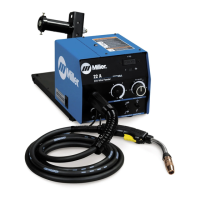
Ref. ST-800 797-C
M-25 And M-25M Feed .023 To .045 in (0.6 To 1.1 mm) Hard Or Flux Cored Wires
Duty Cycle Rating:
100%: 200 A With CO
2
Shielding Gas; 150 A With Mixed Gases
60%: 300 A With CO
2
Shielding Gas; 200 A With Mixed Gases
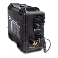
. M-25M is only a replacement gun for MM250MP welding power source
2. Safety Precautions For GMAW Guns
A. Symbol Usage
Means Warning! Watch Out! There are possible hazards with this
procedure! The possible hazards are shown in the adjoining symbols.
This group of symbols means Warning! Watch Out! Possible ELECTRIC SHOCK and HOT PARTS hazards.
Consult symbols and related instructions below for necessary actions to avoid the hazards.
Y Marks a special safety message.
. Means NOTE; not safety related.
B. GMAW Gun Hazards
WARNING
The symbols shown below are used throughout this manual to call attention to and identify possible
hazards. When you see the symbol, watch out, and follow the related instructions to avoid the hazard. The
safety information given below is only a summary of the more complete safety information found in wire
feeder and welding power source manuals. Read and follow all Safety Standards.
ELECTRIC SHOCK can kill.
1. Always wear dry insulating gloves.
2. Insulate yourself from work and ground.
3. Do not touch live electrode or electrical parts.
4. Repair or replace worn, damaged, or cracked gun
or cable insulation.
5. Turn off welding power source before changing
contact tip or gun parts.
6. Keep all covers and handle securely in place.
HOT SURFACES can burn skin.
1. Allow gun to cool before touching.
2. Do not touch hot metal.
3. Protect others from contact with hot metal.
FLYING PIECES OF METAL or DIRT can
injure eyes.
1. Wear safety glasses with side shields or face
shield.
WELDING WIRE can cause puncture
wounds.
1. Keep hands and body away from gun tip when
trigger is pressed.
OVERUSE can damage gun and void
warranty.
1. Follow rated duty cycle.
2. Allow cooling period.
3. Reduce current or reduce duty cycle before
starting to weld again.
1. Read and follow these instructions and all safety
blocks carefully.
2. Have only trained and qualified persons install
operate, or service this unit.
3. Call your distributor if you do not understand the
directions.
4. For WELDING SAFETY and EMF information
read wire feeder and welding power source
manuals.