Do you have a question about the Miller ArcReach SuitCase 12 and is the answer not in the manual?
Explains symbols used for safety warnings in the manual.
Details general hazards associated with arc welding processes.
Presents symbols for installation, operation, and maintenance hazards.
Provides legally required warnings about chemical exposure in California.
Lists key safety standards and where to obtain them for welding.
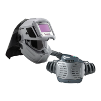
Explains electromagnetic field effects and precautions for medical implants.
Explains additional safety symbols and their meanings.
Defines various symbols used throughout the manual.
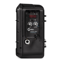
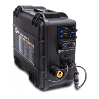
Describes where to find the unit's serial and rating information.
Provides key technical specifications for the welding unit.
Details environmental ratings and operating temperature ranges.
Lists compatible wire types, sizes, and feed speed capabilities.
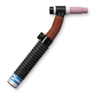
Recommends suitable welding guns for different processes.
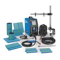
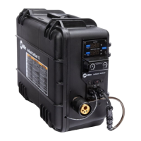
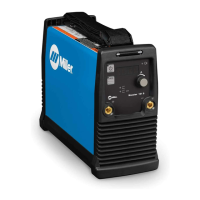
Illustrates how to connect the feeder to the power source and other components.
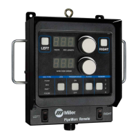
Explains how to utilize ArcReach features with compatible equipment.
Details the process for linking the feeder to ArcReach controls or power sources.
Covers setup procedures for ArcReach and non-ArcReach configurations.
Provides step-by-step instructions for installing drive rolls.
Guides on connecting the welding gun and voltage sensing clamp.
Explains the procedure for connecting the shielding gas supply.
Details how to properly connect the weld cables.
Provides guidance on selecting appropriate weld cable sizes based on current and length.
Covers installing and threading the welding wire into the feeder.
Explains how to configure DIP switches on the motor control board.
Details DIP switch settings for the meter board for display configuration.
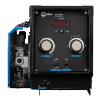
Identifies and explains the function of all controls on the feeder.
Explains the Cable Length Compensation feature and how to use it.
Describes how to use the dual schedule feature for wire speed adjustment.
Provides recommended starting points for wire speed and other weld parameters.
Outlines regular maintenance tasks and schedules.
Explains the unit's overload and thermal protection systems.
Provides instructions for cleaning the shielding gas filter fitting.
Lists common problems and their solutions for the wire feeder.
Explains how to interpret error indicators and diagnostic messages.
Shows an exploded view of the complete feeder assembly with numbered parts.
| Brand | Miller |
|---|---|
| Model | ArcReach SuitCase 12 |
| Category | Welding Accessories |
| Language | English |