EasyManua.ls Logo

Miller SUITCASE 12RC User Manual

Miller SUITCASE 12RC
40 pages
To Next Page IconTo Next Page
Page #1 background imageLoading...
Page #1 background image
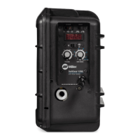
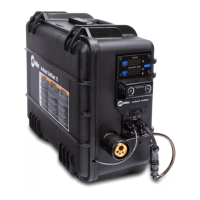
SuitCase 12RC
OM-263984J 2018−02
Processes
Description
MIG (GMAW) Welding
Flux Cored (FCAW) Welding
Wire Feeder
File: MIG (GMAW)
R
CE And Non-CE Models
For product information,
Owner’s Manual translations,
and more, visit
www.MillerWelds.com

Other manuals for Miller SUITCASE 12RC

Questions and Answers:

Miller SUITCASE 12RC Specifications

General IconGeneral
BrandMiller
ModelSUITCASE 12RC
CategoryWelding Accessories
LanguageEnglish

Summary

SECTION 1 - SAFETY PRECAUTIONS - READ BEFORE USING

Symbol Usage

Explanation of symbols used throughout the manual for hazard identification and warnings.

Arc Welding Hazards

Information on potential hazards associated with arc welding processes and equipment operation.

Additional Safety Symbols

Symbols related to installation, operation, and maintenance hazards, including fire, falling equipment, and static.

California Proposition 65 Warnings

Warning regarding exposure to chemicals known to cause cancer or birth defects.

Principal Safety Standards

List of key safety standards and sources for further information on welding safety.

EMF Information

Details on electromagnetic fields (EMF) and their potential interference with medical implants.

SECTION 3 - DEFINITIONS

Additional Safety Symbols

Definitions and explanations for specific safety symbols found on CE products.

Miscellaneous Symbols

Definitions and explanations for various symbols related to electrical, process, and measurement parameters.

SECTION 4 - SPECIFICATIONS

Serial Number and Rating Label

Location of the serial number and rating label for product identification and input power requirements.

Unit Specifications

Detailed technical specifications including input power, wire feed, dimensions, and weight.

Environmental Specifications

Information on IP rating and operating/storage temperature ranges for the equipment.

14-Pin Plug Information

Detailed pinout and function description for the 14-pin connector used for external controls.

Gun Recommendation Table

Table recommending compatible welding guns for different welding processes.

SECTION 5 - INSTALLATION

Equipment Connection Diagram

Visual guide showing how to connect the wire feeder to the power source and workpiece.

Installing Drive Rolls

Step-by-step instructions for installing and cleaning drive rolls for wire feeding.

Connecting Welding Gun

Procedure for securely connecting the welding gun to the wire feeder, including trigger connections.

Connecting Shielding Gas

Instructions for connecting the shielding gas supply to the wire feeder.

Connecting Weld Cable

Procedure for connecting the weld cable between the wire feeder and the power source.

Selecting Cable Sizes

Guideline table for selecting appropriate weld cable sizes based on amperage and cable length.

Installing and Threading Welding Wire

Detailed steps for loading and threading welding wire through the feeder mechanism.

SECTION 6 - OPERATION

Controls Overview

Description of front panel and internal controls, including power, voltage, wire speed, and jog switches.

Digital Meter Board DIP Switch Settings

Guide for configuring DIP switches to set display modes for voltage, amperage, and wire speed.

Timer Model DIP Switch Settings

Instructions for setting DIP switches to configure preflow, burnback, postflow, and re-trigger timing.

SECTION 7 - MAINTENANCE & TROUBLESHOOTING

Routine Maintenance Schedule

Recommended maintenance tasks and schedule for ensuring optimal equipment performance.

Overload and Thermostat Protection

Explanation of overload protection (CB1) and internal thermostat protection mechanisms.

Shielding Gas Filter Cleaning

Procedure for cleaning debris from the shielding gas filter fitting to ensure proper gas flow.

Troubleshooting Guide

Common problems and their remedies for wire feeding issues, power, and operation.

SECTION 9 - PARTS LIST

Complete Assembly Parts

List and diagrams of all parts included in the complete assembly of the wire feeder.

SECTION 8 - ELECTRICAL DIAGRAMS

Wire Feeder Circuit Diagram

Detailed electrical schematic illustrating the circuit board and component connections for the wire feeder.

Wire Feeder Circuit Diagram (Timer PCB)

Electrical schematic for wire feeder models equipped with a timer PCB, showing specific circuit configurations.

Related product manuals