
T
theresasnyderSep 18, 2025
What to do if Miller PipeWorx Welding Accessories show Tach Right?
- PPatricia BrownSep 18, 2025
If this code continues to appear on the display, contact the nearest Factory Authorized Service Agent.
What to do if Miller PipeWorx Welding Accessories show Tach Right?
If this code continues to appear on the display, contact the nearest Factory Authorized Service Agent.
How to fix duty cycle issues on Miller PipeWorx?
To address duty cycle issues with your Miller Welding Accessories, allow the unit to cool for 15 minutes. You may also need to reduce amperage, voltage, wire feed speed, or duty cycle before resuming welding.
What to do if Miller PipeWorx show Primary Input Line Voltage Malfunction?
If you are experiencing a Primary Input Line Voltage Malfunction with your Miller Welding Accessories, increase the primary line voltage to at least 90% of the specified nominal voltage.
How to troubleshoot Serial Communication Loss in Miller Welding Accessories?
If you are experiencing Serial Communication Loss or Malfunction with your Miller Welding Accessories, check the wire feeder/power source control cable connection and tighten it if necessary.
What to do if Miller Welding Accessories show Motor Left?
If this code continues to appear on the display, contact the nearest Factory Authorized Service Agent.
What to do if Miller Welding Accessories show Motor Low Bus?
Increase primary line voltage to at least 90% of specified nominal voltage. If this code continues to appear on the display, contact the nearest Factory Authorized Service Agent.
How to resolve 'Weld Library' error on Miller Welding Accessories?
To resolve the 'Weld Library' issue on your Miller Welding Accessories, the weld library must be loaded from a memory card.
What to do if Miller PipeWorx Welding Accessories show Primary Power Circuit Over Current?
If this code appears on the display, contact the nearest Factory Authorized Service Agent.
What does 'Trigger Fault Left' mean on Miller PipeWorx Welding Accessories?
To address 'Trigger Fault Left' on your Miller Welding Accessories, note that the fault was held too long in trigger jog (the lesser of 60 seconds or 30 ft (9.1 m) of wire.
What to do if the trigger is stuck on the right side of Miller PipeWorx?
To resolve the 'Trigger Stuck Right' issue on your Miller Welding Accessories, release the right trigger.
Explains symbols used for hazard identification.
Details electric shock and other risks during arc welding.
Explains additional symbols related to installation, operation, and maintenance safety.
Lists chemicals known to cause cancer or birth defects.
References key safety standards and their sources for welding and cutting.
Details electromagnetic field effects on medical implants and mitigation procedures.
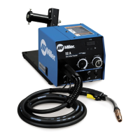
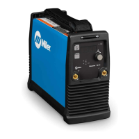
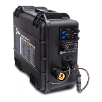
Lists the technical specifications of the PipeWorx Remote Feeder.
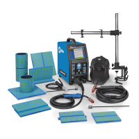
Illustrates how to connect the PipeWorx System, Feeder Remote, and cables.
Details the pinout and function of the PLG6 connector.
Details the pinout and function of the PLG2 connector.
Details the pinout and function of the PLG3 connector.
Details the pinout and function of the PLG4 connector.
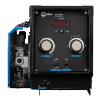
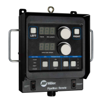
Describes the front panel controls of the remote pendant for welding operations.
Provides an example setup for the left side controls and active settings.
Provides an example setup for the right side controls and active settings.
Outlines routine maintenance tasks and their recommended frequency.
Lists diagnostic codes for power source and feeder malfunctions.
| Welding Processes | MIG (GMAW), Stick (SMAW), TIG (GTAW), Flux-Cored (FCAW) |
|---|---|
| Rated Output | 400 A at 36 VDC, 60% Duty Cycle |
| Max. Open-Circuit Voltage | 78 VDC |
| Compatibility | Compatible with various Miller wire feeders, including Smart Feeders |
| Function | Multi-process welding for pipe fabrication |
| Material | Steel, Stainless Steel, Aluminum |