OM-239 982 Page 14
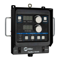
3-4. Remote Interface Cable Connector PLG2 Information
Plug PLG2 Socket* Socket Information
Left Trigger
1 Closure with pin 2 activates left trigger.
2 Closure with pin 1 activates left trigger.
*Sockets 3 and 4 are not used.
3-5. Remote Interface Cable Connector PLG3 Information
Plug PLG3 Socket* Socket Information
Right Trigger
1 Closure with pin 2 activates right trigger.
2 Closure with pin 1 activates right trigger.
*Sockets 3 and 4 are not used.
3-6. Remote Interface Cable Connector PLG4 Information
Plug PLG4 Socket* Socket Information
24 Volts AC Input
3 24 volts AC
6 24 volts AC return. Connected to chassis common. Completes
24 volts AC power supply circuit to remote interface.
Serial Communication
1 Isolated RS-485 (+) serial communication signal.
2 Isolated RS-485 (−) serial communication signal.
5 Isolated serial communication common.
GND 4 Chassis common.
*Socket 7 is not used.
 Loading...
