OM-1035 Page 2
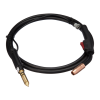
3. Welding Gun Identification
Welding guns can be identified by diamonds on the cable jacket as follows:
M-10: No diamonds
M-15: zz
M-25/M-25M: zzZ
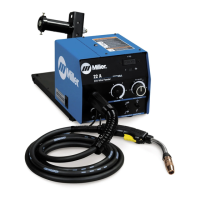
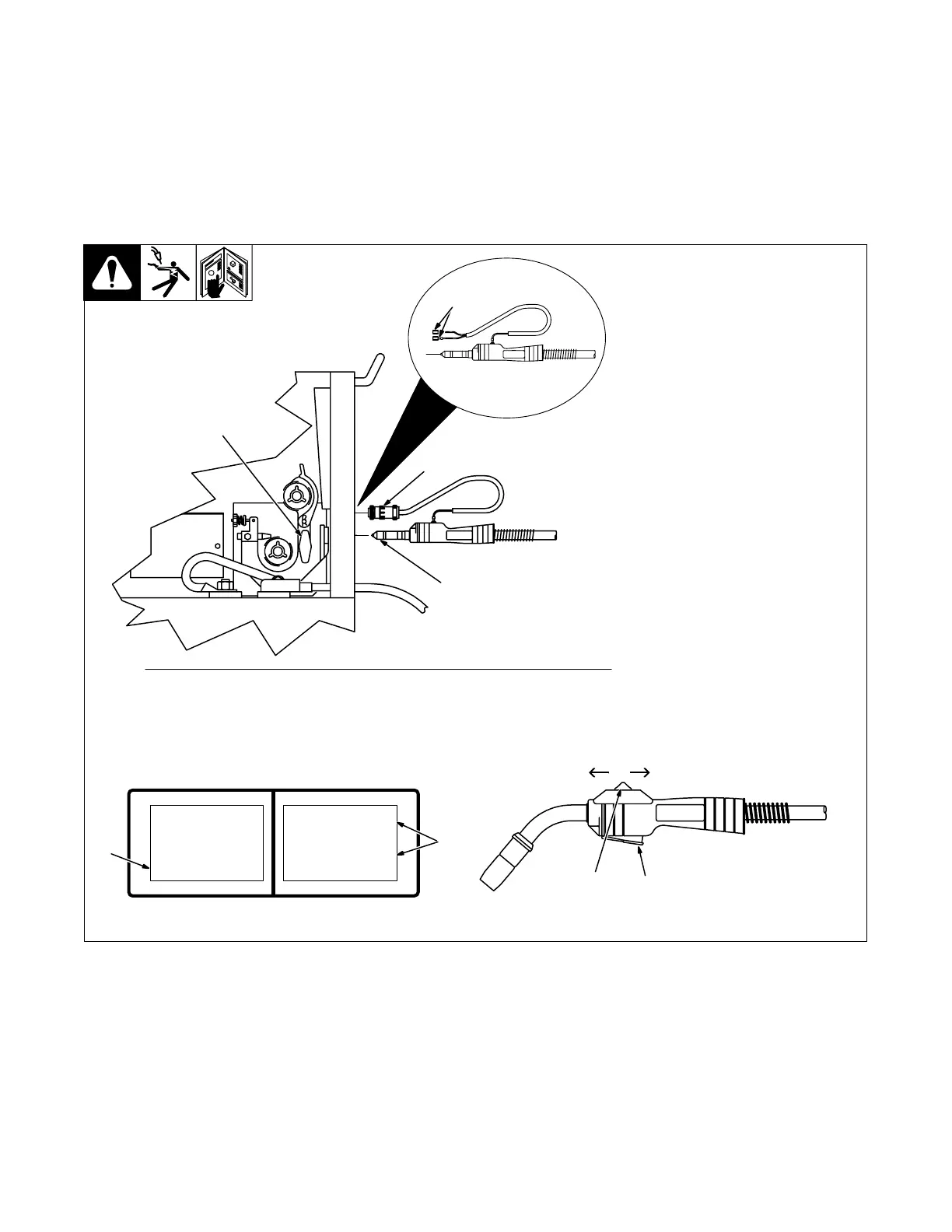
4. Installing Gun And Using The Gun Switch
Ref. ST-800 921-B / ST-801 031
1 Gun Securing Knob
2 Gun End
Loosen knob. Insert gun end until
it bottoms against drive assembly.
Tighten knob.
3 Gun Trigger Plug
Insert into receptacle, and tighten
threaded collar.
4 Friction Terminals
Some applications will require
cutting off trigger plug and
installing 0.250 female friction
terminals onto end of leads.
See wire feeder manual for
threading procedure.
5 Trigger Switch (All Models)
Press switch to feed energized
wire and start gas flow.
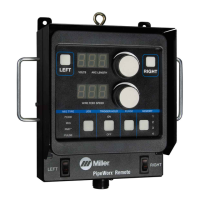
6 Dual Schedule Mode (M-25M
Models)
Select Dual Schedule to set any
combination of the 9 available
memories.
See welding power source for
display data.
7 Switch A Or B And Increase/
Decrease Function (M-25M
Models)
Selects program A or B and
changes wire feed speed.
Ma t e r i a l
We l d
Timer
>D u a l S c h d
Sw i t c h A
>Me m o r y 1
Sw i t c h B
Memo r y 2
(B) (A)+–
5
Wire Speed
6
7
7
1
3
2
Display On Power Source
For M-25M Models Only
4