R
Rachel RoweJul 27, 2025
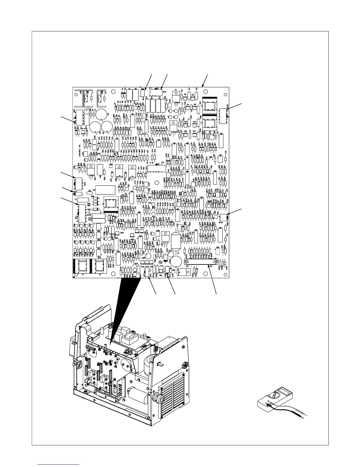
How to fix a Miller Welding System with no weld output and completely inoperative?
- RRobert MorganJul 27, 2025
If your Miller Welding System is completely inoperative with no weld output, start by ensuring the line disconnect switch is in the On position. Then, check and replace the line fuses if necessary, or reset the circuit breaker. Verify that the input power connections are properly connected. After that, check the continuity of the power switch S1 and replace it if needed. Finally, inspect the control transformer T2 for any signs of winding failure, check the continuity across the windings and verify proper connections, and check the secondary voltages; replace T2 if necessary.