
B
Brian HamiltonAug 2, 2025
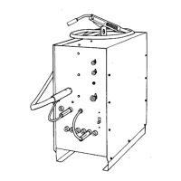
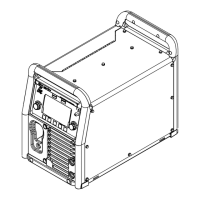
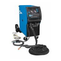
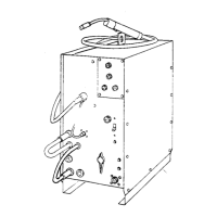
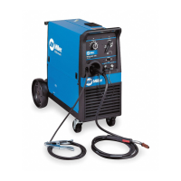
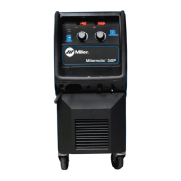
How to fix low weld output on a Miller Millermatic 350 Welding System?
- JJames FreemanAug 2, 2025
To fix low weld output on your Miller Welding System, connect the unit to the proper input voltage or check for low line voltage.