. A complete Parts List is available at www.MillerWelds.com
OM-283935 Page 40
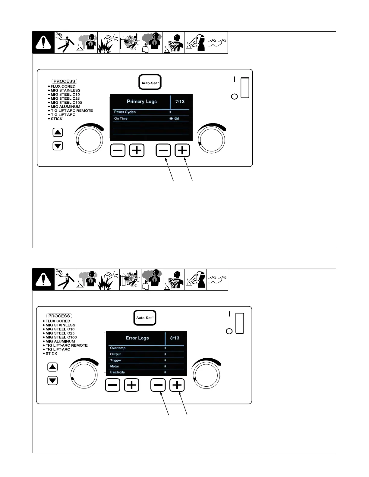
6-10. Primary Logs (Menu 7 Of 13)
1 Lower Right Inside (−) Button
2 Lower Right Outside (+)
Button
Follow instructions in Section 6-3 to
enter the setup menu.
Primary Logs menu displays power
cycles.
To exit menu, simultaneously press
and release the lower left outside
(−) button and lower right outside
(+) button, or turn unit off and on.
Ref. 281104-C
1
2
6-11. Error Logs (Menu 8 Of 13)
1 Lower Right Inside (−) Button
2 Lower Right Outside (+)
Button
Follow instructions in Section 6-3 to
enter the setup menu.
Error Logs screen displays welder
over−temperature errors, shorted
output errors, shorted trigger er-
rors, motor current errors, and
stuck electrode errors.
To exit menu, simultaneously press
and release the lower left outside
(−) button and lower right outside
(+) button, or turn unit off and on.
Ref. 281104-C
1
2