. A complete Parts List is available at www.MillerWelds.com
OM-283935 Page 42
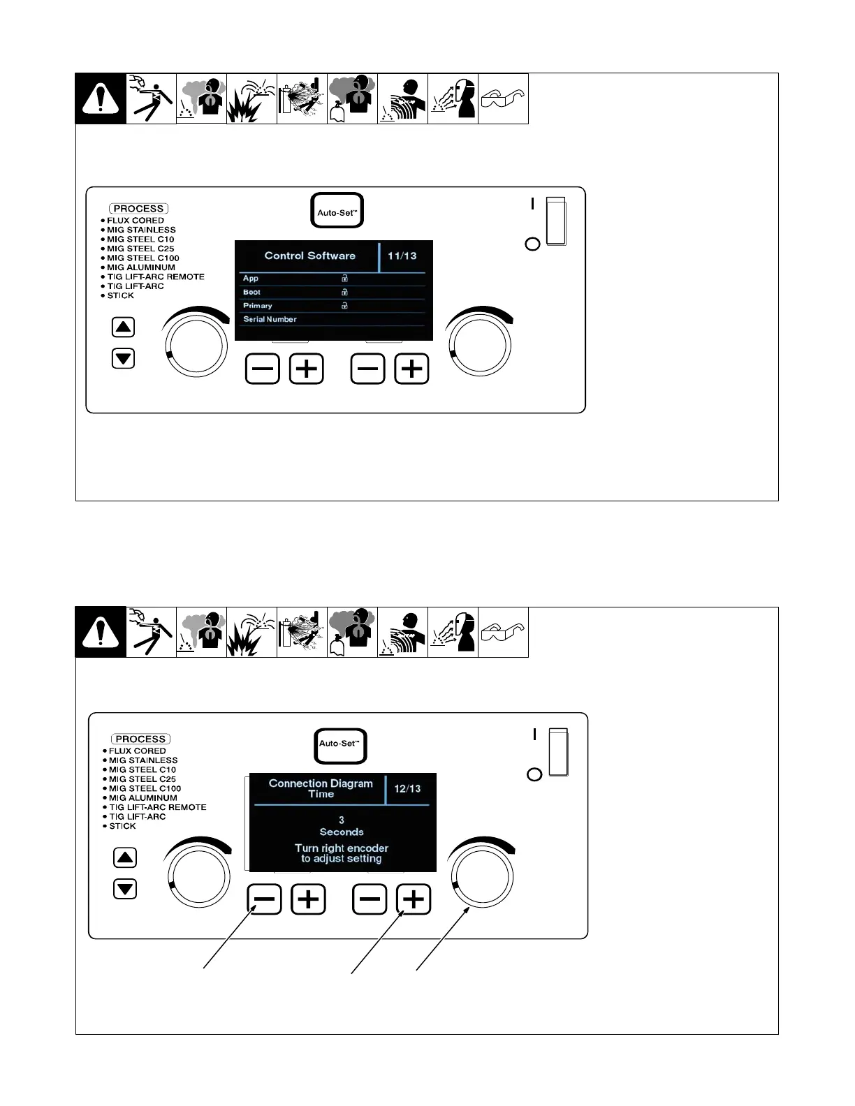
6-14. Control Software (Menu 11 Of 13)
. Control Software information is
for factory and service use
only.
Follow instructions in Section 6-3 to
enter the setup menu.
To exit menu, simultaneously press
and release the lower left outside
(−) button and lower right outside
(+) button, or turn unit off and on.
Ref. 281104-C
6-15. Connection Diagram Time (Menu 12 Of 13)
1 Lower Left Outside (-) Button
2 Lower Right Outside (+)
Button
3 Right Control Encoder
Follow instructions in Section 6-3 to
enter the setup menu.
For intuitive connection set up im-
ages are displayed to help with
proper machine and cable connec-
tions when welding processes are
changed. This time can be adjusted
from Off to 30 seconds. Default time
is 3 seconds.
To exit menu, simultaneously press
and release the lower left outside
(−) button and lower right outside
(+) button, or turn unit off and on.
Ref. 281104-C
1
2
3