Do you have a question about the Miller XMT 400 CC/CV and is the answer not in the manual?
Explains the meaning of warning symbols used in the manual.
Details critical hazards associated with arc welding processes and equipment.
Covers hazards related to installation, operation, and maintenance procedures.
Lists key safety standards relevant to welding and equipment operation.
Discusses considerations about welding and the effects of low frequency electric and magnetic fields.
Provides definitions for symbols found on the manufacturer's warning labels.
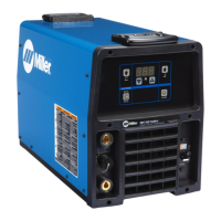
Details the rating labels specific to CE products, including technical specifications.
A comprehensive table defining various symbols used throughout the manual.
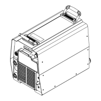
Guidance on choosing an appropriate location and airflow for the welding unit.
Provides the physical dimensions and weight specifications of the welding unit.
Cautionary advice regarding tipping hazards when placing or moving the unit.
Information on weld output receptacles and guidance for selecting appropriate cable sizes.
Details the sockets and their functions for the Remote 14 receptacle.
Details the sockets and their functions for the Remote 17 receptacle.
Description of the 115 Volt AC receptacle, its power output, and usage.
Provides essential electrical service information, including input voltage and amperage.
Instructions on how to correctly place jumper links to match the input voltage.
Step-by-step guide for safely connecting the input power to the welding unit.
Detailed explanation of all controls and indicators on the front panel of the unit.
Information on duty cycle, potential overheating, and protective measures.
Outlines recommended routine maintenance tasks and schedules.
Procedure for safely removing the top case and measuring capacitor voltage.
Identification and function of circuit breakers and fuses within the unit.
Instructions on how to select and configure the meter hold function.
Lists common problems encountered and provides remedies for resolution.
Presents the detailed electrical circuit diagram for the welding power source.
Lists components and their part numbers for the main assembly of the unit.
Details parts and components associated with the front panel assembly.
Lists components and part numbers related to the mid-chassis assembly.
| Input Frequency | 50 / 60 Hz |
|---|---|
| Output Current Range | 5 - 400 A |
| Power Factor Correction | Yes |
| Protection Class | IP23 |
| Input Phase | Single or Three Phase |
| Rated Output | 300 A at 32 V |
| Duty Cycle | 60% at 400 A |
| Welding Processes | MIG (GMAW) Stick (SMAW) TIG (GTAW) Flux-Cored (FCAW) |
| Input Voltage | 208/230/460 V |