C
HAPTER
6 - M
AINTENANCE
39
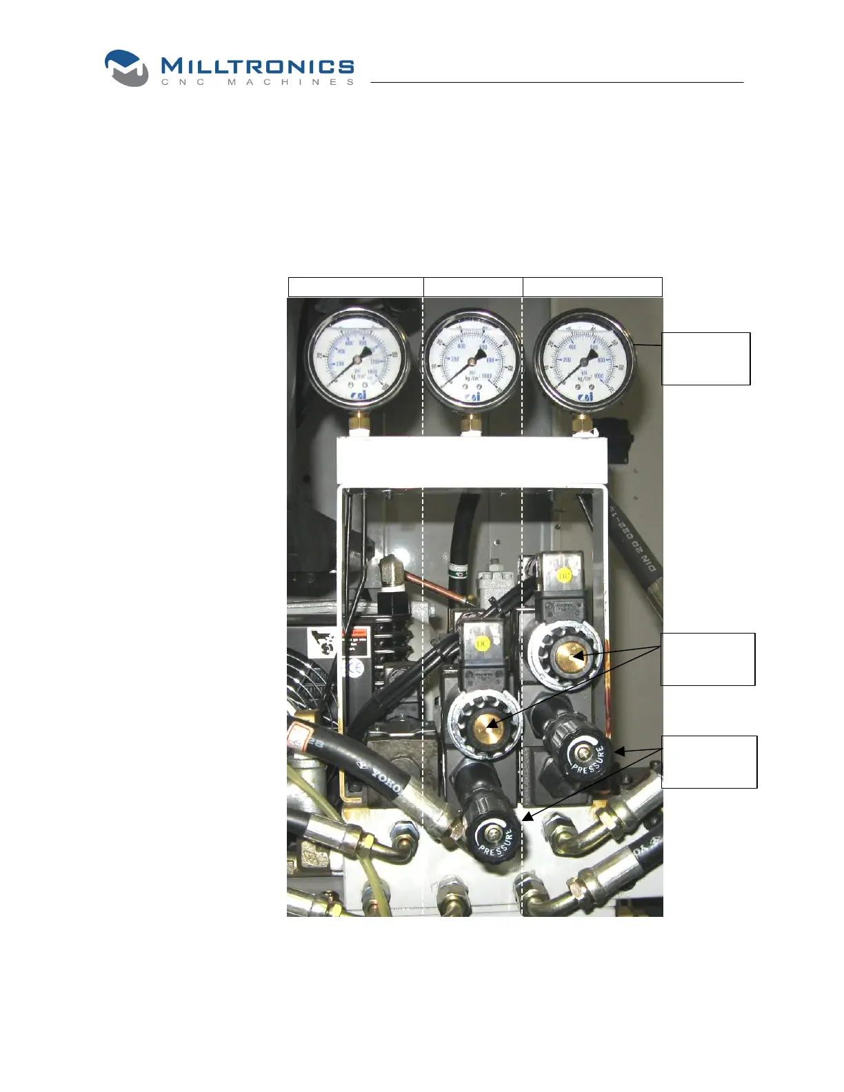
Hydraulic Valves, Pressure Switches, and Gauges
Manual
actuators
Pressure
adjustment
Pressure
gauges
Front View
Parts Catcher Chuck Tailstock
Pressure Regulators
The pressure regulators
are factory set to
200psi. Each regulator
should be adjusted
according to specific job
requirements.
There is no regulator for
the parts catcher valve.
Pressure adjustments
are made using the
to the right where the
larger number
represents higher
pressure, and lower
number represents
lower pressure.
Manual Actuation
The valves can be
actuated manually by
pressing the buttons
shown here and on the
following page.
Switches
When pressure
adjustments are made,
the switches (see
following page) must be
adjusted accordingly.
The factory setting for
the switches is 190psi.
The illustration below shows the arrangement of the hydraulic valves and gauges on
SL6-10 model turning centers. See the following page for additional views.