Do you have a question about the Milltronics SL12 Series and is the answer not in the manual?
List of safety instructions to follow before operating the machine.
Essential safety guidelines, including DANGER and WARNING notices.
Guidelines on appropriate attire and personal protective equipment for safe operation.
Safety precautions during workpiece machining and tool handling.
Safety guidelines to be followed when performing machine maintenance.
Critical safety information regarding electrical hazards and procedures.
Procedures and precautions to prevent entrapment in the machine.
Importance of reading and understanding safety labels on the machine.
Identifies and describes various safety and maintenance labels on the machine.
Specifications for the weights of different SL machine models.
Electrical current and voltage specifications for machine operation.
Details on the coolant tank capacities for various SL models.
Guidance on selecting appropriate coolants for the machine.
Specifications for the hydraulic fluid tank capacity.
Information on accessing control instructions and specification documents.
Details on tool shank sizes and boring bar sizes for SL lathes.
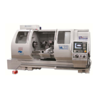
Diagram showing the physical layout and dimensions of the SL12 series machine.
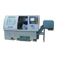
Identification of key components on the SL10 machine model.
Guidelines for selecting and preparing a suitable location for machine installation.
Essential electrical power and grounding requirements for machine setup.
Instructions for connecting a transformer to the machine's power supply.
Diagram illustrating autotransformer wiring for various voltage selections.
Requirements and adjustments for the machine's air supply system.
Preferred and safe methods for moving the machine.
Specific procedures for lifting the machine using a crane or hoist.
Guidance on the initial setup and checkout process for the machine.
Steps for assembling parts that may have been removed for shipping.
Detailed steps for leveling the machine accurately.
Specifies the maximum allowable taper for the SL lathe headstock.
Procedures for initial inspection of the machine's components, guards, and safety systems.
Basic inspection points for the machine's overall condition and completeness.
Verification of electrical connections and safety rules before operation.
Ensuring all protective guards are correctly installed and functional.
Procedures for verifying the safe operation of the machine's systems.
Steps to initialize the machine's axis positions.
Procedure to verify the functionality of the emergency stop system.
Procedure to verify the functionality of the machine enclosure safety interlocks.
Practices to reduce everyday wear and tear on the machine.
Methods for resolving faults related to electrical components.
Techniques for identifying and assessing mechanical issues within the machine.
Scheduled maintenance tasks and safety system checks.
Outline of maintenance tasks based on frequency (Always, Daily, Weekly).
Specific safety checks to perform monthly and post-maintenance.
Procedures for maintaining the machine's air system.
Instructions for maintaining the way lubrication system.
Maintenance procedures for the LS-200 tool turret.
Routine checks and replacement of hydraulic system components.
Adjusting pressure settings for the hydraulic tailstock and chuck.
Maintenance and adjustment of hydraulic chuck pressure and switches.
Overview and description of the controls on the 7200 CNC front panel.
Visual representation of the main CNC control screen layout.
Displays detailed information on the CNC control's current state.
Operating procedures for C-axis and optional live tooling.
Commands for selecting between the main and live tooling spindles.
Operating the C-axis for positioning and movement.
How to use the jog function for the spindle when the door is open.
Notes and examples for performing drilling and tapping operations.
Features and options for conversational programming.
List of parts and diagrams for the hydraulic chuck.
List of parts and diagrams for the spindle transmission system.
List of parts and diagrams for the spindle speed detector.
List of parts and diagrams for the headstock with C-axis option.
List of parts and diagrams for the optional parts catcher.
List of parts and diagrams for the optional cut-off detector.
List of parts and diagrams for the X-axis assembly.
List of parts and diagrams for the Z-axis assembly.
List of parts and diagrams for the tailstock.
List of parts and diagrams for machine guarding.
List of parts and diagrams for the door guarding.
List of parts and diagrams for the electrical box guarding.
List of parts and diagrams for air FRL and parts catcher solenoid.
Checklist to be completed to activate the machine warranty.
Customer's responsibilities during machine installation and setup.
Milltronics representative's responsibilities during machine setup and verification.
Checks to be performed on the magnetic panel connections.
Procedures to verify incoming power and transformer wiring.
Procedures to reset the machine and prepare for potential axis runaway.
Tests and checks related to the machine's spindle operation.
Checks for the turret's tool change functionality.
Checks for the operation of the optional hydraulic chuck.
Checks for the operation of the hydraulic tailstock.
Checks for the operation of the optional chip conveyor.
Checks for the operation of the optional parts catcher.
Steps for leveling the machine and checking taper adjustment.
Section for customer sign-off on installation and warranty terms.
| Spindle Speed | 5000 rpm |
|---|---|
| Spindle Motor | 20 hp |
| Spindle Bore | 1.75 inches |
| X-Axis Travel | 6.3 inches |
| Z-Axis Travel | 20 inches |
| Tailstock Quill Travel | 4 inches |
| Rapid Traverse Rate (X/Z) | 945 ipm |