!
DANGER
!
Do not open the door to any electric box without first turning the power OFF. These con-
trols use 240VAC power OR HIGHER, which is extremely dangerous.
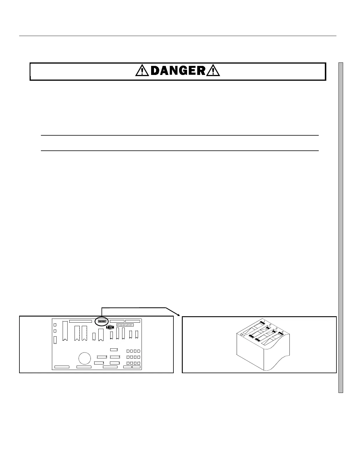
The DIP switches on the microprocessor board are shown in Figure 3. The ON/OFF positions are shown in
Figure 4. Set the switches to the desired configuration according to the table below. Turn the machine ON. The
display will show the current configuration chosen during power-up.
C
D
ÎFIGURE 3
(MSOP0244AE)
ÎDIP Switch Location on Processor Board
Industry
Configuration
CORRECTIONAL
HOTEL/MOTEL
ATHLETIC
HEALTHCARE
RESTAURANTS
COMMERCIAL
SHIRT LAUNDRY
OFFSHORE
S1
OFF
ON
OFF
ON
OFF
ON
OFF
ON
S2
OFF
OFF
ON
ON
OFF
OFF
ON
ON
Switch Settings
S3
OFF
OFF
OFF
OFF
ON
ON
ON
ON
S4 S5 S6
*Switch S4 in the ON position activates Split Fill Configuration. (System 7 Control only)
**Set switch S5 to ON in Q6G models otherwise these models will skip drain speed and try to
enter extract from wash speed. This will overload or perhaps stall the extract motor and likely
cause it to fail.
Set switch S5 to OFFin Q4G models otherwise these models will skip E1 (extract speed) and try
to enter E2 (high speed extract) from the distribution speed. This will overload or perhaps stall
the extract motor and likely cause it to fail
(Switch S5 setting doesn’t matter on MxG models.)
***Setting switch S6 ON enables the operator to cancel any step in progress, except a drain.
Split Fill Configuration
*
Depends on model
**
OFF prevents/ON permits
skipping steps.
***
In this example,
switches 1 thru 4
are OFF,ON,ON,
OFF, respectively.
ÎFIGURE 4
(MSOP0244AE)
ÎDIP Switch ON/OFF positions
SYSTEM 7 MICROPROCESSOR SOFTWARE MSFD0802AE/8946DV (3 of 5)