14
19, Item 865) and coupling (860) to allow fre e
rotation of ECC shaft.
5. Ap ply po wer to ECC an d allow it to run to it s
new position at a zero mA signal. Ensure t he
capacity control knob did not rotate.
6. Ap ply a 4 mA signal to place ECC in r everse-
acting mo de. This is now the 1 00% capacity
setting.
7. With ECC and pump capacity knob at 10 0%
capacity setting, carefully slide the ECC shaft
back into th e co upling a nd re place th e fo ur
mounting screws. If req uired, rotate the pump
adjustment sc rew to allow ass embly. Do not
move the ECC shaf t. On MaxRoy B pumps
tighten coupling nut (Figure 19, Item 865) and
coupling ( 860) (Approximately 4 0 lb . ft.). Pin
should remain in approximate mid point of slot
in coupling.
8. Che ck operation th rough full signa l ra nge an d
recalibrate if required (See ECC Calibration,
Section 4).
3.2.2 Input Signal
The ECC is sh ipped from the factor y a djusted to
accept a 4-20 mA command signal. If the unit is to
be operated with any other range, it must be set up
for that range.
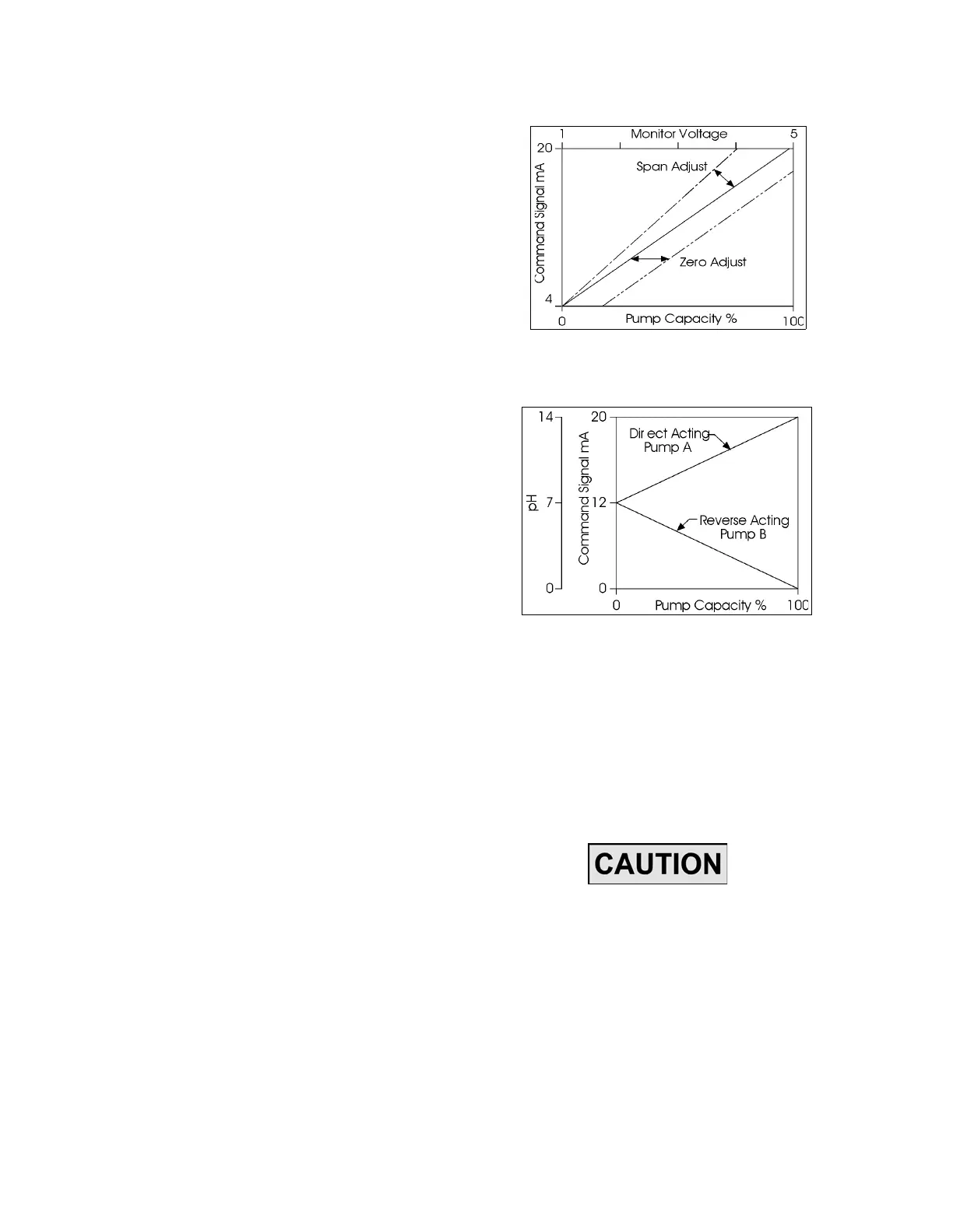
• Adjusting the span control, VR1, Figure 11,
determines th e m aximum tr avel o f t he
ECC over the full r ange o f the com mand
signal.
• Adjusting the zero control, VR2, Fig ure 11
shifts the position of this travel (Figure 9).
The ECC ma y b e set up to op erate over a “split
range” of either 0 to 10 0% capacity corresponding
to a 12 to 20 mA signal, or 0 to 100% capacity cor-
responding to a 1 2 to 4 mA sign al ( in r everse
action mode) - such as pumps A & B in a typical pH
control system, shown in Figure 10.
Figure 9. Effect of Zero & Span Controls.
Figure 10. Split Range Operation w/Two Pumps
(Typical pH Control System).
3.3 CONTROL RANGE ADJUSTMENT
First remove the cover from the ECC. On the ECC-
circuit bo ard, Figu re 1 1, a re four lig hts an d four
small tr im pote ntiometers. The light s are in pairs.
The pots are for zero, span, upper limit, and lower
limit adjust.
THE LIMIT POT ENTIOMETERS MUST
BE SET BEFORE CHANGING THE CON-
TROL RANGE. THEY MUST BE
ADJUSTED (AS THEY ARE AT THE
FACTORY) TO PREVENT OVERTRAVEL
OF THE CONTROL SPOOL. IMPROPER
ADJUSTMENT OF THESE UPPER AND
LOWER LIMIT TRIM POT S MAY
RESULT IN DAMAGE TO THE PUMP OR
THE ECC.
www.motralec.com / service-commercial@motralec.com / 01.39.97.65.10