15
1. Energize the ECC with AC power.
2. Make sur e that the ap propriate jumper p lugs
have already been either removed or installed
to establish the desired mode of actio n (direct
action or reverse action) as described earlier in
this section.
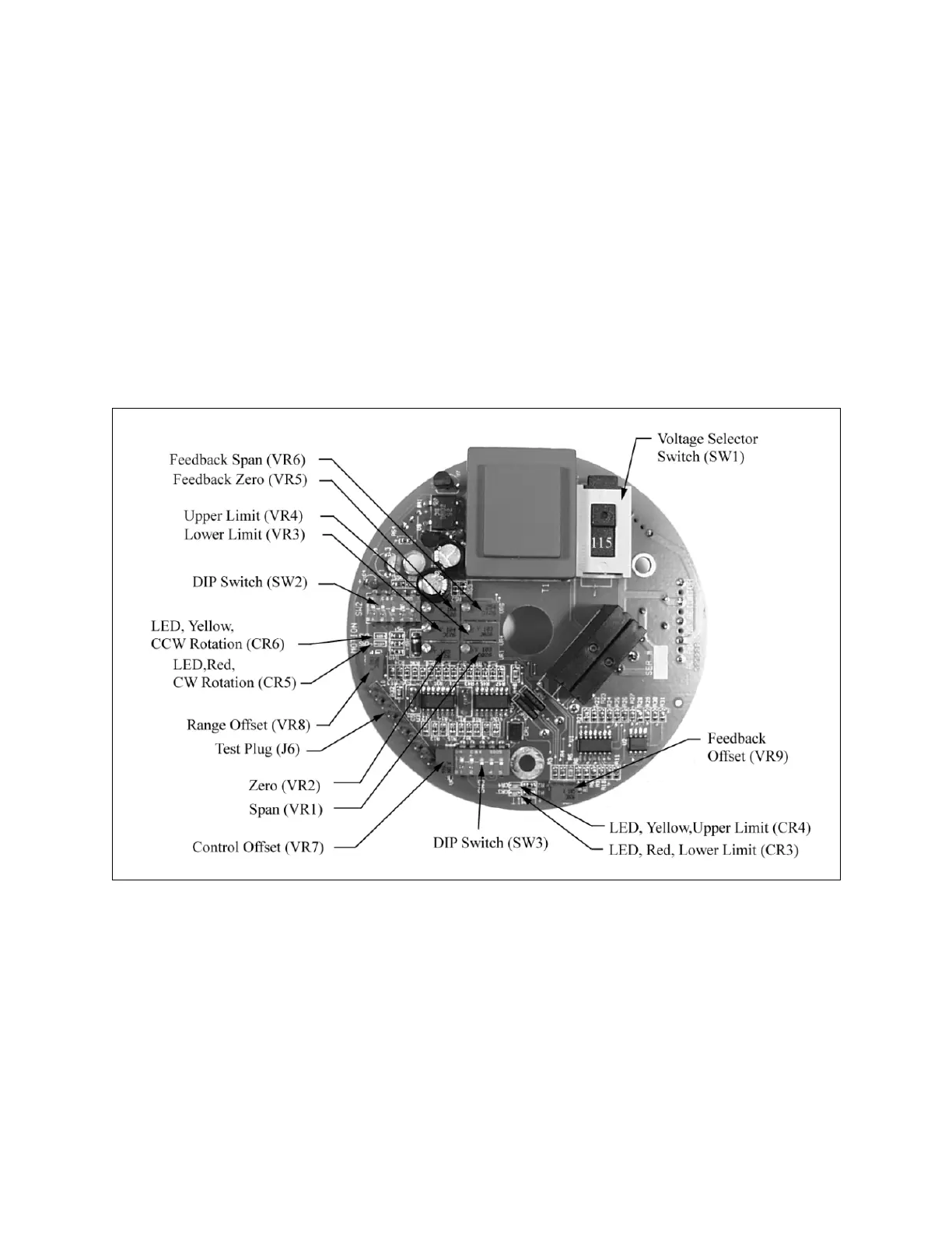
3. Locate th e “ Zero” ( VR2) and “ Span” ( VR1)
adjust contr ols on the pr inted circuit bo ard
(PCB) shown in Figure 11.
4. Apply the lower limit input signal to the unit. For
a 4-20 mA operating range, this signal will be 4
mA; (f or a 1 2-20 m A ra nge, th e lo wer sig nal
will be 12 mA).
5. Turn the “Ze ro” ( VR2) adjust control until the
pump cap acity ind icator rin g move s to the
desired po int or until no further adjustment is
possible, whichever comes first.
6. Apply the upp er limit inpu t si gnal to th e unit
(this will be 20 mA).
7. Turn th e “ Span” ( VR1) a djust contr ol un til th e
pump cap acity control knob moves to the
desired point.
8. Repeat S teps 4 thr ough 7 un til the de sired
results are achieved.
Figure 11. Circuit Board, Top.
www.motralec.com / service-commercial@motralec.com / 01.39.97.65.10