Hardware Overview Theory of Operation
1 - 4 0070-10-0604-01 Duo™ Service Manual
1.2.2 Fan Driver Board Overview
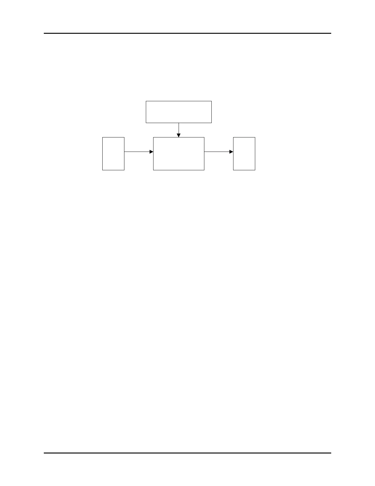
The Fan Drive Board is active during the battery charging cycle. The Temperature Detector
senses the temperature of the heat sink of the Secondary Rectifier diode and turns on the fan
when the heat sink reaches a certain temperature.
FIGURE 1-3 Fan Driver Block Diagram
1.2.3 CPU/Display Board Overview
The CPU/Display board controls the SpO
2
Module and NIBP Module through
communications via UART devices. The CPU Board receives user commands from the
Keypad. The power supply board provides +3.3 vdc and +12 vdc to the CPU board. These
voltages are monitored by an A/D converter located on the CPU board. The CPU also
controls an integral LED display array and indicator LEDs. The main processor has a built-in
serial port that is used to load software. The processor also uses a FPGA to communicate
with the NIBP Module, the optional SpO
2
module (SpO
2
presence is detected via a jumper
on JP1) and to drive the LED arrays and indicators.
Fan Driver Board Test Points
Location Function
Measure across C202 +5 vdc Fan power.
C202 Negative Lead Ground.
Measure between Q202 pin1 and Ground Drive frequency when the Fan is activated.
Temperature
Detector
DC
Input
Fan Driver
Circuit
Fan