Hardware Introduction
2-19
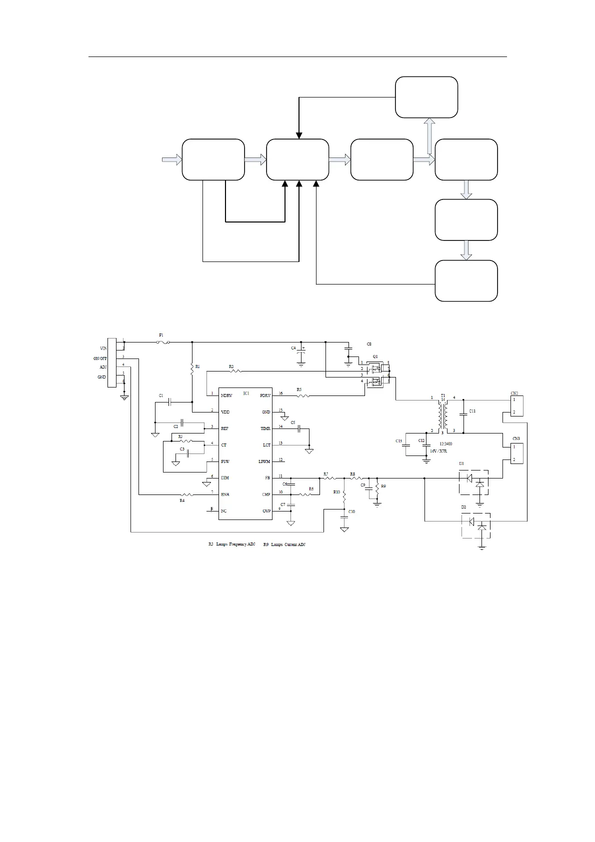
Regulating
board
PW/M
control
Voltage
feedback
MOSFET
switch
13.5V input
Boost
conversion
Output to
strip lamp
Current
feedback
Inverter module
Brightness control
On/Off
Block Diagram of LCD Inverter
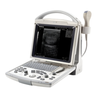
Functional Diagram of LCD Inverter
The input of the inverter module is a 13.5V DC from the regulating board. In the inverter
module, the on-off MOSFETs are connected as a bridge circuit, which implements the
on-off operations driven by the main IC and convert the input DC to high voltage AC and
then transmit to the primary winding of the transformer. The secondary square wave of
the transformer is converted to sine wave after LC resonance to drive the CCFL gives out
light. The on-off signals control the on and off of the strip lamp throuth the enabling pin of
the main IC. The brightness of the light is controlled by the brightness signal, which will
control the duty cycle of square wave of main IC.
The inverter module is configured with protection circuit of open circuit, overvoltage and