9-34 Structure and Assembly/Disassembly
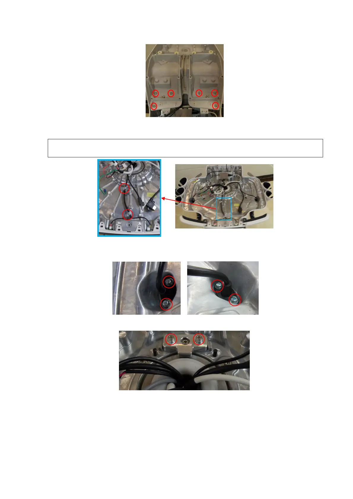
9. Unscrew 2 M4 X 12 cross panhead screws on UC-0.5 lock knob with screwdriver (M3, M4) to
remove the wires.
The orientation and the position of the fixing clip should keep same with these in the
following figure.
10. Unscrew 4 M4 X12 cross panhead screws with screwdriver (M3, M4) to remove the connection
wires of the coupling gel heating cup.
11. Unscrew 2 M5 X 16 round inner head screw (with the pad) from the stop block by M5 spanner.
12. Unscrew six M5 X 16 round inner head screws from the keyboard base with the M6 inner
hexagon spanner. Rotate the base assembly anticlockwise until exposing the electrical magnet
(electromagnet 120 kgf) (separating the electromagnet), and the lift base assembly straight
(FRU).
 Loading...


