Principles of Operation
2-4
2.2.1 Main Board
2.2.1.1 Principle diagram
CPU
PHY
RTL8201
RTC E2PROM
Audio process
circuit
FlashSDRAM
SPI
Serial port 1: NIBP
Watchdog
RS232
LCD
KEY
Serial port 0
Serial port 3: Temp
Serial port 2: SpO2
RS232 IC
Serial port 4: Recorder
Ethernet
Linear power
3.3V
1.5V
5.0V
Speaker
LED
FPGA
Nurse Call
12V
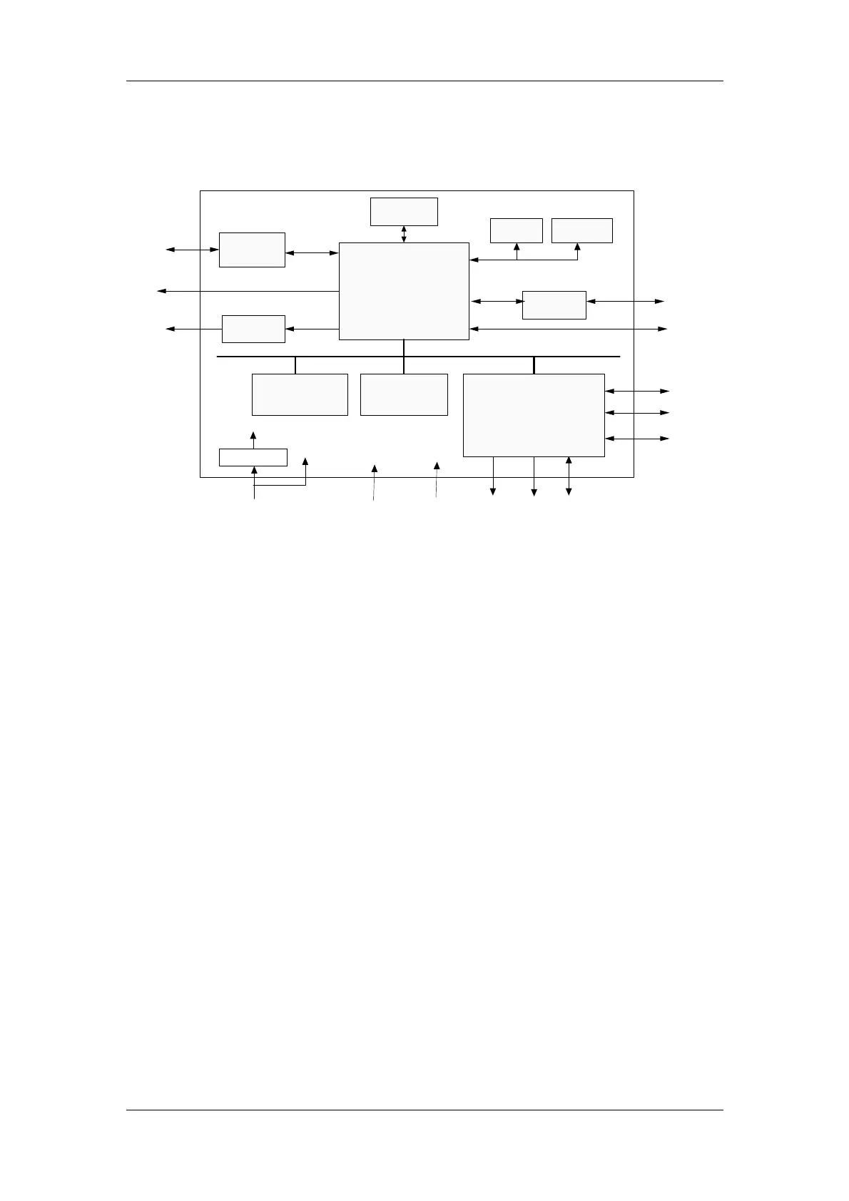
Figure 4 Operation principle of the main board
2.2.1.2 Principle
The main board communicates with all parameter modules and recorder module through serial
ports; the power of the parameter modules is adapted from the main board.
The main board supplies displaying information for the key&displays board detects the keys
and realizes the user’s interface.
The audio process circuit of the main board drives the speaker, thus to realize audible alarms,
key tones and PITCHTON.
The main board controls the alarm indicator through the signal wire is adapted from the
key&displays board.
In addition, the main board provides the nurse call connector, network connector and R232
connector.
The real-time clock is realized by the RTC chip to which the power is supplied from AC mains
or by the battery when available. When the AC power or battery is unavailable, the built-in
battery of the RTC chip supplies the power, thus guaranteeing the normal working status of the
clock.
SDRAM is responsible for storing data temporarily and running programs; FLASH serves as
the system program memory and trend data memory; E
2
PROM serves as the device
configuration memory.