3
3. Connection and installation method
3−1. INPUT connector
(1) Pin layout
Pin No.
Signal name
1 Differential motion signal of torque(+)
2 Differential motion signal of torque(−)
3 +15 V
4 GND
5 −15 V
6 GND
7
Quantity of light decrease detection output signal
8 COM1
9 Power supply signal to rotor
10 Power supply signal to rotor
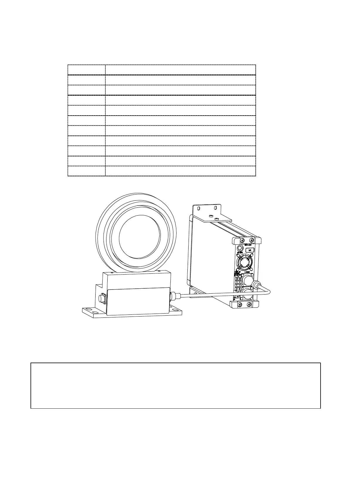
(2) Connection with stator
CSA−562B
Stator
P/N of connector plug
CSA−562B :SRCN6A16−10P (JAE)
Stator :TC1108−12A16−14M 11.8 (Tajimi musen)
● Please use the cable attached with torque transducer in connecting the instrument
with stator. And, don’t extend the cable by using the terminals because it will cause
Moreover, please do not extend the cable with a terminal block etc., because it is easily
influenced by the outside noise, and it causes the accuracy decrease.
Consult us when the length is insufficient in a standard attached cable.