8
4. Calibration method
4−1. Calibration method of torque
There are two kinds of methods of the torque calibration of this instrument.
1
Electrical calibration
The calibration is made electrically by the attached combination inspection data sheet.
2
Actual torque transducer
The calibration is made by applying the rated torque to the torque transducer.
4−2. Preparation before adjustment
Supply the power upon confirming if the torque transducer and power supply are connected
correctly. (Refer to the paragraph 3−3.)
Please take the warming−up of about 15−20 minutes to make this instrument work stabilizing
though this instrument becomes a working condition after turning on the power supply.
4−3. Electrical calibration
Procedure
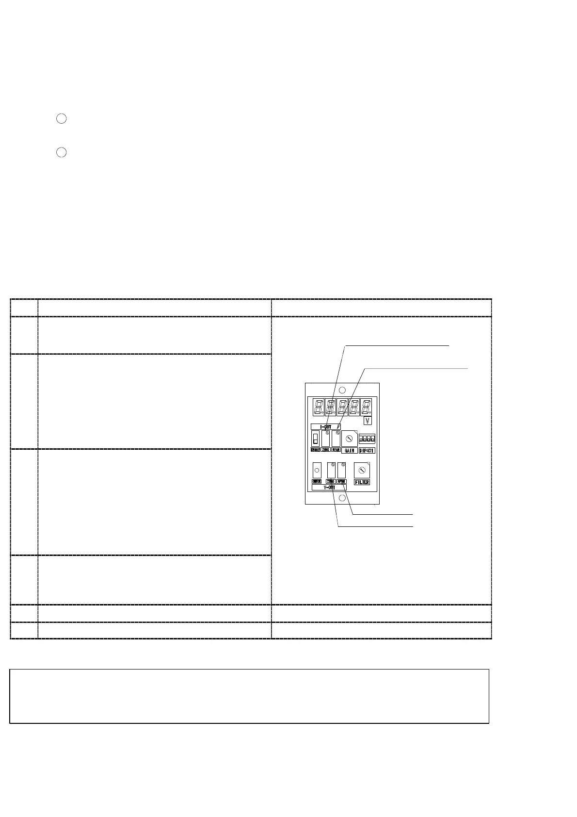
1
The torque transducer is put into the conditon
that an initial torque (condition built into the
device) applys.
ZERO trimmer for
current output
2
Cancel th
initial torque
Adjust the voltage output to 0.000 V or the
current output (option) to 12.00 mA by turning
the ZERO trimmer.
When the voltage output is used together with the
current output (option), the voltage output is
previously adjusted, and then, the current output
(option) is adjusted.
r
mmer
or
voltage output
3
Span adjustment
The output voltage is matched by using SPAN
trimmer to become the CHECK value described in
the inspection data sheet while pressing the
CHECK switch.
When the voltage output is used together with the
current output, the voltage output is previously
adjusted, and then the current output (option) is
adjusted.
SPAN trimmer
ZERO trimmer
4
Readjustment of ZERO point
Leave the had from CHECK switch, and proceed
the step 2 again to adjust the voltage output to
0.000 V and the current output to 12.00 mA.
5
Please confirm step 2 to 4 again.
6
Calibration is completed.
● The output from the Torque transducer will be + voltage output in the counterclockwise
direction and − voltage output in clockwise direction.
The output polarity for the Torque transducer is fixed and can’t be changed.