4
3−2. OUTPUT connector
(1) Pin layout
Pin No.
Signal Name Cable color
1 Voltage output(+) Red
2 Voltage output(−) Red/White
3 Current output(+)(Option) Black
4 Current output(−)(Option) Black / White
5 External input for check switch Yellow
6 Common for external input Yellow / White
7 ALARM output Green
8 Common for ALARM output Green / White
9 No use
10 No use
P/N of connector plug :SRCN6A16−10S (JAE)
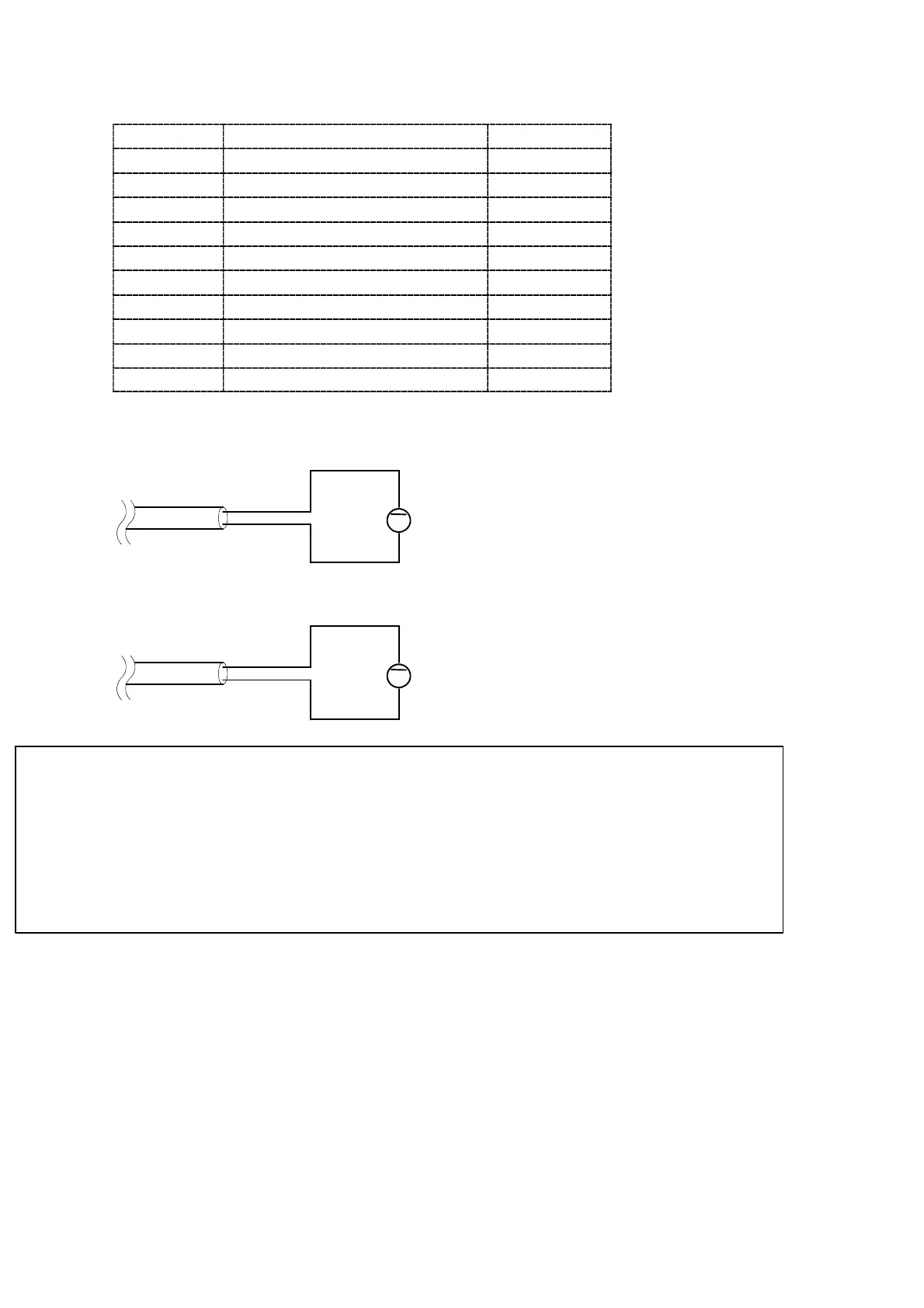
(2) Connection of voltage output
+
−
V
to D.V.M. or sequencer
Red
Red / White
(3) Connection of current outptu(Option)
+
−
Black
A
to D.V.M. or sequencer
Black / White
● As for standard unit, the electric current output is not adjusted.
● Execute the adjustment of current output after completing the adjustment of voltage
output. When the procedure is made oppositely, the adjusting condition of current
output changes.
● Connection of the instrument with the stator (In the case of the stator is grounded.)
makes the voltage output (−) and current output (−) to the same potential as the
ground potential