FACTORY CHECKOUT AND REPAIR
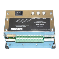
If it is determined that a problem exists within the
SCRB-68, it can be returned to the factory for checkout
and repair. Before returning the unit, contact the Min-
ster Repair Parts Department for a Returned Goods
Authorization number (RGA#). This will ensure the
timely return of the repaired unit.
When returning a unit to the factory for repair, make
certain it is carefully packaged to protect it from dam-
age during shipment. Include, with the unit, the RGA#,
a description of the problem(s) encountered and the
serial number of the press on which it is used. Also
include your purchase order covering the work to be
performed and any special shipping instructions con-
cerning return of the unit.
Ship To: The Minster Machine Company
115 North Ohio Street
Minster, Ohio 45865-0120
ATTN: RGA# ________
SPECIFICATIONS
Supply
• Voltage: 100-125VAC
• Power: 900W
• Frequency: 48 to 62 Hz
Input/Output Characteristics
• Coupling: 90VDC-115VDC, 900W
• Brake: 90VDC-115VDC, 900W
• Tachometer: 30-60VAC, 300-800Hz
• Relay Output: 110VDC, 200mA
Miscellaneous
• Dimensions (L × D × H): 231mm (9.125 in.) × 140mm
(5.5 in.) × 130mm (5.125 in.)
• Temperature Range: 0°C to 60°C (32°F to 140°F)
— 19 —
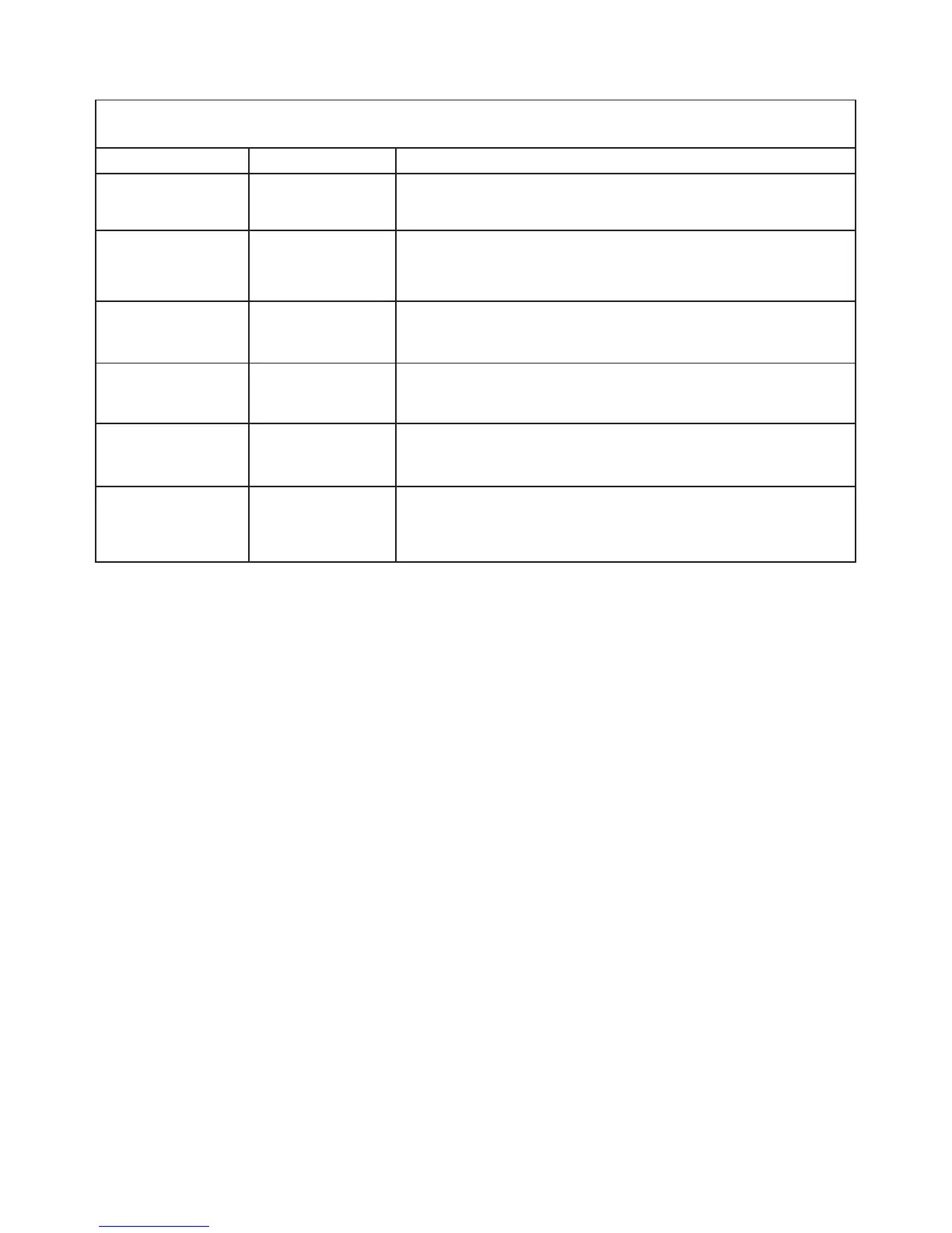
VOLTAGE GUIDE
TERMINALS FUNCTION VOLTAGE REQUIRED WITH DRIVE RUNNING
1 to 2
(Signals D to Y2)
A.C. Supply Voltage 100 Volts A.C.
5 to 15
(Signals F1/C1 to
K1/K3)
D.C. Supply Voltage 90 Volts D.C., 5 (-) and 15 (+)
5 to 3
(Signals F1/C1 to
F2/C2)
Coupling Coil
Excitation Voltage
Normally 5 to 10 Volts D.C. with flywheel only running. Could
increase to 90 volts D.C. with coupling fully energized. 5 (-) and 3 (+)
7 to 12
(Signals G1 to G2)
Tachometer Voltage Approximately 30 to 60 Volts A.C., depending on speed of drive.
8 to 7
(Signals P1 to G1)
Reference Voltage Approximately 16 Volts D.C., 8 (+) and 7 (-)
7 to 9
(Signals G1 to R)
Selected
Reference Voltage
0 to 16 Volts D.C. depending upon setting of speed potentiometer.
7 (-) and 9 (+).