EasyManua.ls Logo

Minster SCRB-68 - User Manual

Minster SCRB-68
24 pages
Print Icon
To Next Page IconTo Next Page
Loading...
Manual No. 679A
MINSTER®
8952-574
SCRB-68
EDDY CURRENT COUPLING CONTROLS
DESCRIPTION
OPERATION
MAINTENANCE
REPAIR PARTS
MINSTER SOLID STATE CONTROLS
$5.00

Questions and Answers

  • W
    Whitney SmithAug 3, 2025
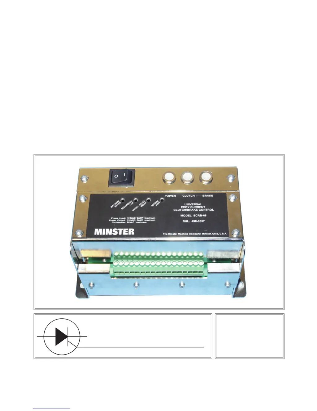
    What to do if Minster SCRB-68 unit runs only at full drive motor speed?
    • D
      Destiny Lloyd DDSAug 3, 2025
      If your Minster Industrial Electrical unit runs only at full drive motor speed, first ensure the issue is electrical by checking the coupling excitation on terminals 5 (F1/C1 signal) and 3 (F2/C2 signal). Also, verify the D.C. voltage between terminals 9 (R signal) (+) and 7 (G1 signal) (-) is zero when the speed potentiometer is turned down. Check for tachometer feedback voltage, A.C., between terminals 7 (G1 signal) and 12 (G2 signal). If the drive continues to run after turning the power switch off, the drive has likely failed due to a locked center bearing or a closed air gap in the coupling.
  • J
    joshua28Aug 14, 2025
    What to do if Minster Industrial Electrical unit does not run after drive motor has started?
    • A
      Andrea JonesAug 14, 2025
      If your Minster Industrial Electrical unit does not run after the drive motor has started, ensure that 100 volts A.C. exists between terminals 1 (D signal) and 2 (Y2 signal) when the power switch is on. Also, check that the operator’s speed potentiometer is providing a reference signal to the control. Verify the D.C. output voltage on coupling terminals 5 (F1/C1 signal) and 3 (F2/C2 signal), and check the setting of the torque limit control.
  • C
    clarkdanielAug 25, 2025
    Why does my Minster Industrial Electrical unit slowly drift in speed?
    • S
      Samuel Long MDAug 25, 2025
      If your Minster Industrial Electrical unit slowly drifts in speed, try these steps: 1. Reset the torque limiting point as per the manual's instructions, as the torque limiter may be incorrectly set. 2. Inspect the speed control potentiometer for wear or loose wiring connections to the control terminal strip. 3. Note that operating the drive at low output speeds can cause excessive loading and slow the unit down. 4. Check for erratic tachometer feedback voltage, A.C., between terminals 7 (G1 signal) and 12 (G2 signal).

Summary

SERVICE AND WARRANTY INFORMATION

DESIGN CHANGES

Discusses potential variations in components due to manufacturing updates.

REGARDING WARRANTY

Refers to the warranty documentation included in the service manual.

COMPONENT IDENTIFICATION

SCRB-68 Unit Views

Diagrams showing the SCRB-68 unit with cover removed and rear view.

DESCRIPTION AND OPERATION

OPERATION

Details how to operate the press drive motor and speed controller.

EXPLANATION OF EDDY CURRENT COUPLING

SCRB-52;58 Coupling Control Schematic

Schematic diagram of the SCRB-52/58 coupling control.

EDDY CURRENT BRAKE

SCRB-42;48 Coupling;Brake Control Schematic

Schematic diagram of the SCRB-42/48 coupling/brake control.

FUNCTION OF THE SPEED SENSE RELAY

CHASSIS AND PANEL MOUNTED COMPONENTS

Unit Indicators, Controls, Transformer, and Fuses

Describes indicators, power switch, transformer, and fuses on the unit.

SCRB-52;58 Coupling Control Layout

Diagram showing the SCRB-52/58 coupling control layout.

ADJUSTMENTS

Maximum Speed Potentiometer Adjustment

Adjustment for matching the tachometer generator.

Maximum Speed Potentiometer Adjustment Procedure

Step-by-step guide for max speed potentiometer adjustment.

ADDITIONAL ADJUSTMENT PROCEDURES

Torque Limit, Speed Sense Relay, and SPM Meter Adjustments

Procedures for adjusting torque limit, speed sense relay, and SPM meter.

REFERENCE OUT (PLC ANALOG INPUTS)

CONTROL REPLACEMENT

Option A: SCRB-52;58 to SCRB-68 Conversion

Procedure to replace a SCRB-52/58 control unit with a SCRB-68.

SCRB-52;58 Replacement Worksheet

Wiring worksheet for replacing SCRB-52/58 with SCRB-68.

OPTION A: SCRB-52;58 TO SCRB-68 CONVERSION (CONTINUED)

Safety Precautions for Option A Installation

Warnings about drilling hazards and hazardous voltages during installation.

OPTION B: SCRB-42;48 TO SCRB-68 CONVERSION

SCRB-42;48 Replacement Worksheet

Wiring worksheet for replacing SCRB-42/48 with SCRB-68.

OPTION B: SCRB-42;48 TO SCRB-68 CONVERSION (CONTINUED)

Safety Precautions for Option B Installation

Warnings about drilling hazards and hazardous voltages during installation.

OPTION C: SCR-22;28 TO SCRB-68 CONVERSION

SCR-22;28 Replacement Worksheet

Wiring worksheet for replacing SCR-22/28 with SCRB-68.

OPTION C: SCR-22;28 TO SCRB-68 CONVERSION (CONTINUED)

Installation Notes and Considerations

Notes on troubleshooting, component availability, and drive motor care.

TROUBLESHOOTING GUIDE

Unit Does Not Run After Drive Motor Starts

Checks for when the unit does not run after motor start.

Unit Slowly Drifts in Speed

Checks for when the unit exhibits speed drift.

Unit Runs Only at Full Drive Motor Speed

Checks for when the unit only runs at full speed.

Fuses Blow

Checks for when fuses blow.

VOLTAGE GUIDE AND SPECIFICATIONS

VOLTAGE GUIDE

Details voltage requirements for various terminal functions.

FACTORY CHECKOUT AND REPAIR

Instructions for returning the unit to the factory for service.

SPECIFICATIONS

Lists technical specifications of the SCRB-68 control.

Minster SCRB-68 Specifications

General IconGeneral
BrandMinster
ModelSCRB-68
CategoryIndustrial Electrical
LanguageEnglish