— 14 —
Option B: Conversion from a SCRB-42/48 to a
SCRB-68
When replacing a SCRB-42 Control Unit with a SCRB-
68 Control Unit, (2) 3.2 Amp fuses must be installed in
the 100 volt AC power-in circuit and when replacing a
SCRB-48 Control Unit , (2) 10 Amp fuses. The first fuse
is to be installed in series with the terminal 1; the sec-
ond fuse is to be installed in series with the terminal 2
of the SCRB-68 control.
Follow the procedure outlined below to replace the
SCRB unit and install the two fuses.
1. Place the POWER, OFF-ON selector switch in the
OFF position and lock the electrical disconnect
switch in the OFF position. Then open the electrical
control panel to obtain access to the SCRB-42/48
unit.
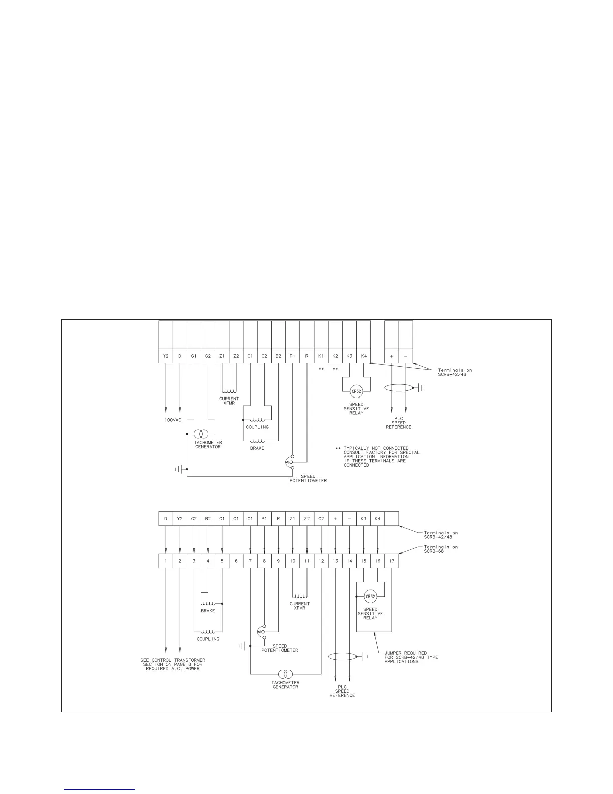
2. Disconnect the wires from the terminals on the
SCRB-42/48 unit. The wires will be re-connected to
the new unit, therefore, make certain the wires are
labeled before disconnecting them. Also the correct
wire number from the wire being taken off of the
SCRB-42/48 should be written into the blanks
above the terminals on Figure 7.
3. Loosen the four (4) mounting screws that secure
the SCRB-42/48 unit to the panel just enough to
permit removal of the unit. Then remove the unit
from the control panel.
4. Install the SCRB-68 unit in the control panel and
tighten the four (4) associated mounting screws
securely.
5. Connect the wires (previously removed in Step 2) to
the terminals on the SCRB-68 unit. Refer to Figure
7 for wiring details.
NOTE: A jumper must be installed between termi-
nals 15 and 17 on the SCRB-68. Failure to
install this jumper will result in an inoperable
SCRB-68.
6. The two (2) fuse holders (furnished) should be
installed as close to the 100 Volt transformer as
Figure 7. SCRB-42/48 replacement worksheet.