EXPLANATION OF
EDDY CURRENT COUPLING
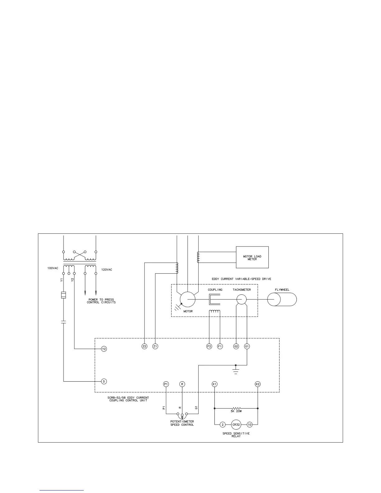
(See Figure 3)
Before entering into a circuit description of the Eddy
Current Coupling Control, a few preliminary remarks
regarding the principle of eddy current coupling will be
noted. This brief description is offered merely to estab-
lish a common background for describing the control
application.
The principle of eddy current coupling makes it possi-
ble to obtain a wide range of stepless, adjustable
speeds directly from industrial A.C. power lines at stan-
dard frequencies. The drive unit consists of a constant
speed induction motor and an integral magnetic clutch,
or eddy current coupling, assembled in a common
housing. The variable speed output shaft is rotated by
the constant speed A.C. motor through the eddy cur-
rent coupling.
The eddy current coupling usually consists of three
basic members: the driving member or drum assembly,
the driven member or rotor assembly, and a stationary
member which is the field coil assembly. These basic
components are illustrated schematically in Figures 3
and 4.
A high strength iron drum is connected to the driveshaft
of the constant speed motor and rotates at the speed of
the motor. This drum is the driving member and, in prin-
ciple, serves as a series of conductor loops as well as
a magnetic flux carrier. The position of the drum is such
that its inner surface surrounds and partially encloses
both field coil and rotor.
The variable speed output shaft is a part of the rotor
assembly and rotates at speeds determined by the
control setting. The cylindrical portion of the rotor lies
between the drum and field coil assemblies and is
divided into magnetically isolated sections by a non-
magnetic metal ring called a magnetic barrier. Poles,
cast into each rotor section, project alternately across
the outer surface of the rotor and are isolated from the
inner surface of the drum by an air gap. As the field coil
is excited, each rotor section assumes a polarity oppo-
site to that of the other section and becomes alternate
north and south magnetic poles.
The field coil assembly is a stationary toroidal coil locat-
ed concentrically within the rotor assembly. When the
coil is excited, magnetic lines of force emanate from it,
flowing through the north poles of the rotor into the
drum, through the south poles of the rotor and back to
the field assembly. As the drum rotates, the direction of
—6—
Figure 3. SCRB-52/58 Coupling control.