13
INSTALLATION
General
Installation must be carried out in accordance with these instructions, and must be
conducted by designated, qualified and competent personnel.
1. Before commencing, make sure that the installation conditions comply with the
information given in section: ‘Specifications’.
2. Care must be taken during installation to prevent any risk of injury or damage.
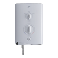
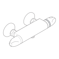
3. The mixing valve should be positioned for easy access during use and
maintenance. All routine maintenance procedures can be conducted with the
mixing valve body in place (except for strainer and checkvalve access). For all
models, allow a minimum 80 mm clearance in front of the temperature control to
enable removal of the serviceable parts during maintenance.
4. The use of supply-line or zone strainers will reduce the need to remove debris at
each mixing valve point. The recommended maximum mesh aperture dimension
for such strainers is 0.5 mm.
5. Pipework must be rigidly supported.
6. Pipework dead-legs should be kept to a minimum. The mixed outlet water piping
should not exceed 2 m and the overall length from the hot water circuit to the
discharge point should not exceed 5 m.
7. Supply pipework layout should be arranged to minimise the effect of other outlet
usage upon the maintained pressures at the mixing valve inlets.
8. Inlet and outlet threaded joint connections should be made with PTFE tape or
liquid sealant. Oil-based, non-setting jointing compounds should not be used.
9. To eliminate pipe debris it is essential that supply pipes are thoroughly flushed
through before connection to the mixing valve.
 Loading...