Wiring
2
DIP SWITCH DSW1 is used to set the preferred signal zone 1 output, the signal silence inhibit, and
the common trouble flash rate. The default output for the signal zone is temporal code.
• Temporal Code: 3 rounds of 0.5 second ON, 0.5 second OFF, then 1.5 second pause.
• Steady: Signal on continuously.
Wiring
Detection Zone
The system has one detection zone. Refer to Figure 3 on page 7 for wiring instruction and to Figure
4 on page 8 for wire size.
Signal Zone
There is one signal zone available for bells and horns providing 1.7A of signal power. Refer to
Figure 3 on page 7 for wiring instruction and to Figure 5 page 8 on for wire size.
Alarm and Trouble Relays
Alarm and trouble relay contacts are provided. Refer to Figure 6 on page 9 for contact location and
designation.
Note: Any time the DIP switches in DSW1 are positioned (ON or OFF), the panel must
be reset by holding the Reset button for 5 seconds.
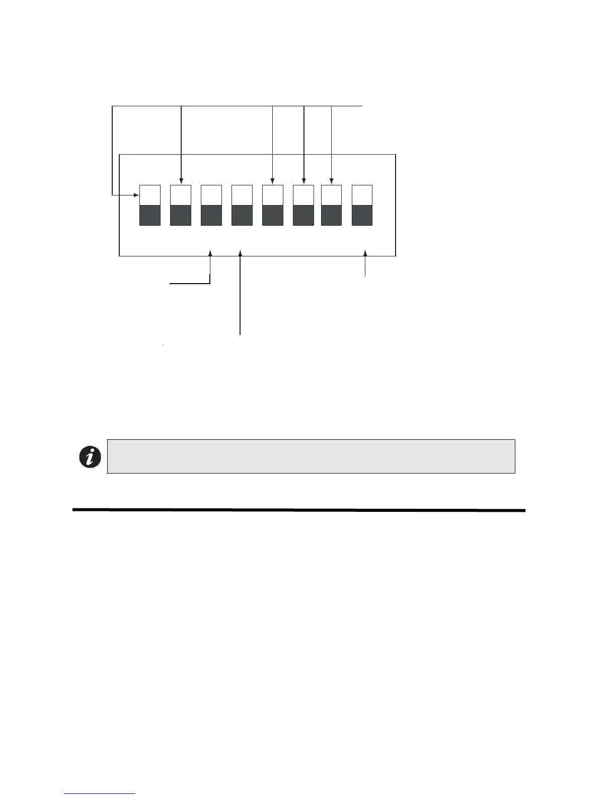
1 2 3 4 5 6 7 8
ON
not used
Trouble Buzzer and LED
ON - steady buzzer and LED
OFF - Pulsing Buzzer and LED (default)
ON - 1 minute signal silence inhibit
OFF - normal signal silence (default)
Signal Zone
ON - steady
OFF - temporal code (default)
DIP switch DSW1