LT- 1087 Rev. 0 Nov 2010 Page 2 of 2
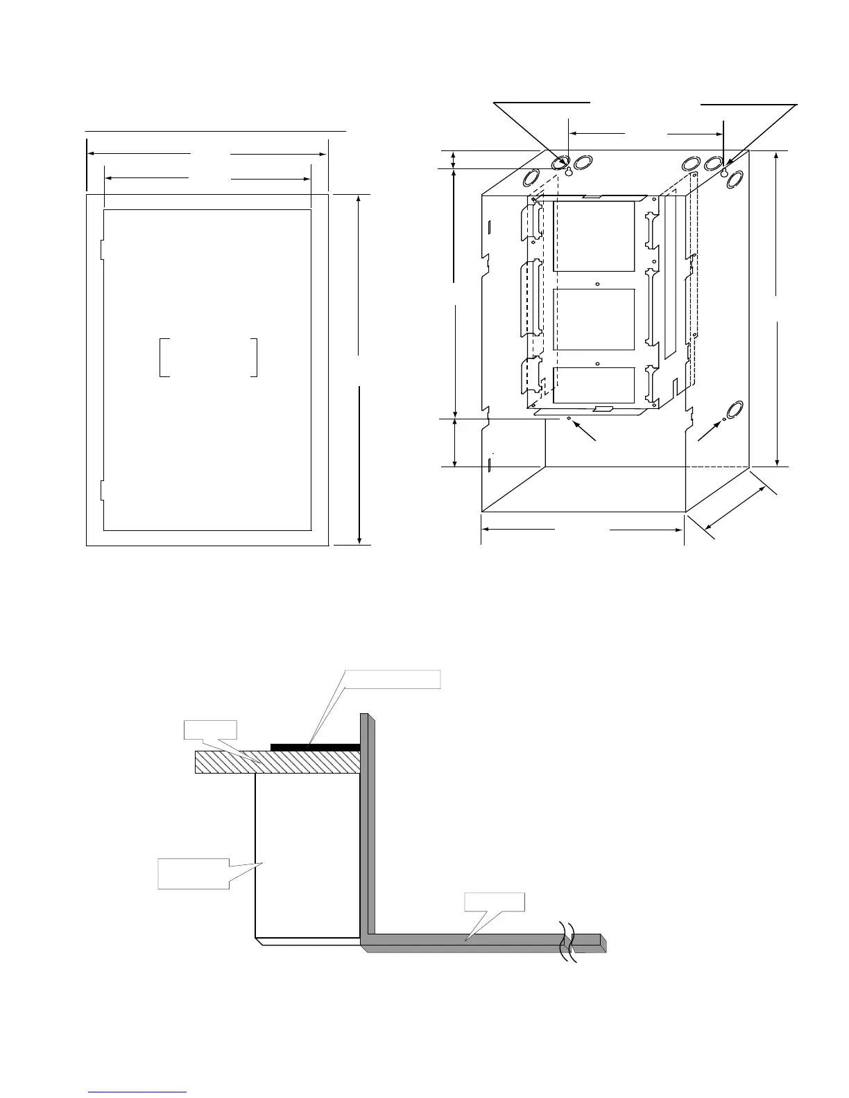
Figure 2: Backbox and Trim Ring Dimensions for Models FX-351-LW/-LDW/-LDR,
FX-353-LW/-LDR, FA-301-8LR/-8LW/-8LDR/W and FA-301-12LR/-12LW,
FA-301-12LDR/-12LDW, FA-301-12DDR
Mounting the Boards to the Chassis
The main board is mounted to the chassis and is shipped out this way. All adder modules are mounted in the same manner
as explained in the respective fire alarm manual.
Figure 3: Cross-Section of Flush Mounted Backbox
Wiring
All wiring is as explained in the respective fire alarm panel manual.
Mounting Holes
Mounting Holes
11”
20.5”
1.5”
14.5”
14.5”
26”
4”
4.5”
17”
28.5”
Adhere trim ring to
wall surface around
the FA-300 backbox.
PLACE FA-UNIV-TRB TRIM RING OVER BACKBOX
TRIM RING
WALL
WOOD OR
METAL STUD
BACKBOX
 Loading...


