FleX-Net
TM
Installation and Operation Manual
35
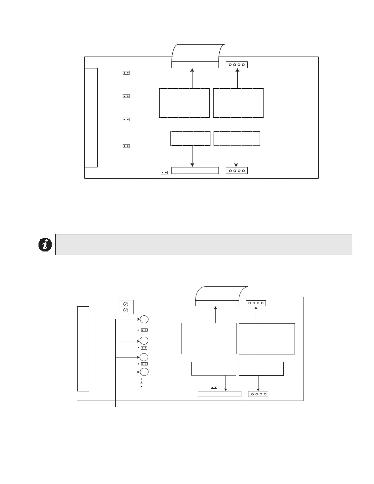
Hardwire Detection Adder Module ( DM-1008A)
Figure 20: Hardwire Detection Adder Module ( DM-1008A)
JW1: Install jumper for Class A operation of initiating circuits 1 and 2.
JW2: Install jumper for Class A operation of initiating circuits 3 and 4.
JW3: Install jumper for Class A operation of initiating circuits 5 and 6.
JW4: Install jumper for Class A operation of initiating circuits 7 and 8.
JW5: Remove continuity jumper if there are any more adder modules installed.
Hardwire Signal Adder Module (SGM-1004A)
Figure 21: Hardwire Signal Adder Module (SGM-1004A)
Basic Mode
Jumpers on the SGM-1004A Signal Adder Module and their functions:
JW1: Remove continuity jumper if this is not the last adder module installed.
Note: For Class A operation the FX-2000N must be configured as Class A via the configuration
program.
P1
P3
P4
FI ELD WI RI NG TERM I N ALS
P2
JW 5
JW 4
JW 3
JW 2
JW 1
Data cable to P6 or P5 of
main fire alarm module or to
P13 or P12 of hardwire
loop controller module, or
previous adder module
Powe r connector to P8 of
main fire alarm module,
or to P2 of hardwire loop
controller module, or to
previous adder module
Dat a conn e cto r f or
next adder module
Power con ne ctor fo r
next adder module
P1
P3
P4
FIELD WIRING TERMINALS
P2
JW1
JW5
JW4
JW3
JW2
J11
1 2 3
GREEN SIGNAL LEDs
ZONE 4
ZONE 3
ZONE 2
ZONE 1
Data cable to P6 or P5 of
main re alarm module
or to P13 or P12 of loop
controller module, previ-
ous adder module
Power connector to P8 of
main re alarm module, or
to P2 of loop controller
module, or to previous
adder module
Power connector for
next adder module
Data connector for
next adder module
1
2