14
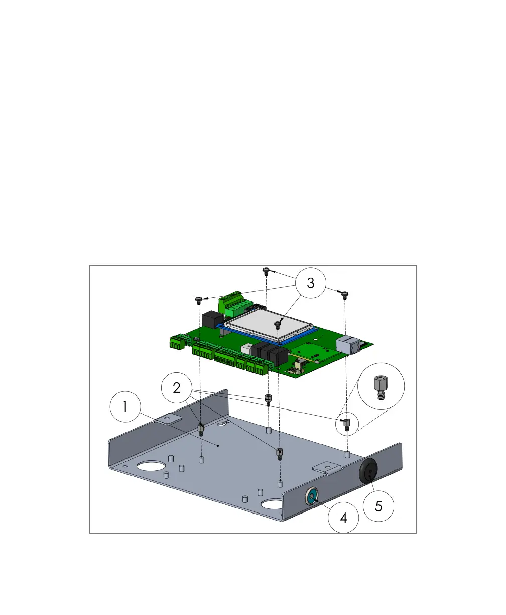
FlatPak Retrot (see Figure 4)
1. Remove Legacy PCB hardware from existing FlatPak enclosure.
2. Extend standoffs by installing the four included standoffs (1/4” x #6–32) on
top of the existing standoffs on the enclosure back plane.
3. Secure the MyDro PCB into the enclosure by placing it on top of the
extended standoffs, use existing #6–32 screws.
4. Remove existing key reader and replace it with the one supplied. Terminate
the new key reader at the bottom right side of the PCB.
5. Remove the old noisemaker and ll the hole with the supplied knock-out plug.
The PCB includes an onboard noisemaker.
6. Replace lid with new one supplied when installation and testing is complete.
Figure 4:
FlatPak Retrot
 Loading...