4
INSTALLATION
General Information
Installation of the diaphragm pump is easy. However, if installation characteristics recommended
by the manufacturer company are considered, working life of the pump shall be long and have
high efciency. (see page 4, gure 1). It should be paid attention that there is no leak and ow
from thread connections when air or uid connection components (hoses, pipes, ttings material
and etc.) are interconnected while installing the diaphragm pump. All connection components
should be pressurized well. If necessary, uid seal should be used.
• All bolt and nut connections should be controlled before installing the diaphragm pump and
it necessary it should be re-tightened. There may be loosening in these connections due to
vibrations that the pump suffered during carrying.
• If there is pressure difference more than 25% between air pressure entering in the diaphragm
pump and outgoing uid pressure, the pump operates inefciently. Transferred uid is very
dense. This situation may be prevented by increasing weights of balls used as check valve or
by using stainless steel marbles.
• Rubber wedge should be placed under pump stands in a place where installation is made
while installing the diaphragm pump. This is recommended by the manufacturer company.
Rubber wedge decreases tensions to pump, prevents dissolution of bolts from vibration and
also prevents material fatigue.
• Diaphragm pump installation should be made to uid to be transferred at a close distance as
far as possible.
• Suction line length and ttings number should be kept at a minimum during installation.
• Diameter of suction line of the installed pump should not be decreased to smaller diameters.
• If pipe line is not exible in a place where diaphragm pump was installed, exible hose should
be positioned between pipe line and pump.
3
12
4
9
5
2
4
3
3 6
11
13
7
10
8
7
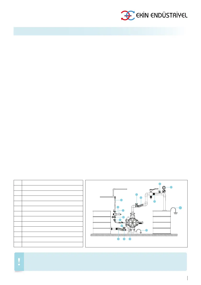
The following (Figure 1) installation type is to give user company enlightening information about how installation
should be made and to guide. Consult to Ekin Endüstriyel or authorized dealer for more information and document.
444 35 46 (EKIN)
1 Aodd Pump
2 Fluid Relief Valve
3 Fluid Shutoff Valve
4 Flexible Fluid Outlet Loine
5 Manometer
6 Rubber Wedge
7 Ball Valve (To Control Air Flow)
8 Manometer (Air Pressure Measurement)
9 Air Filter / Regulator Assembly
10 Air Supply Line
11 Pump Ground Wire
12 Grounding Wire
13 Fluid Drain Valve
Figure 1