8
List of Figures
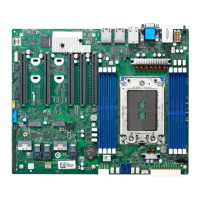
Figure 2-1. Major Components of System Board.........................12
Figure 3-1. Connector and Jumper Locations..............................16
Figure 4-1. Inserting CPU ............................................................19
Figure 4-2. Installing CPU............................................................20
Figure 4-3. DIMM Socket Locations.............................................21
Figure 4-4. Installing DIMM Module .............................................22
List of Tables
Table 2-1. Major Components Description ..................................13
Table 3-1. Internal Connector Definition ......................................17
Table 3-2. External Connector Definition .....................................17
Table 3-3. CPU Jumper Settings .................................................18
Table 3-4. CMOS Jumper Settings ..............................................18
Table 5-1. Keyboard Usage in the SETUP Program....................24