12
Picture 15
Picture 16
Picture 14
4.9.2 Vertical clamp adjustment
The vertical clamp height can be adjusted by the side-handle.
Proceed as follows toproperly position the vertical clamp:
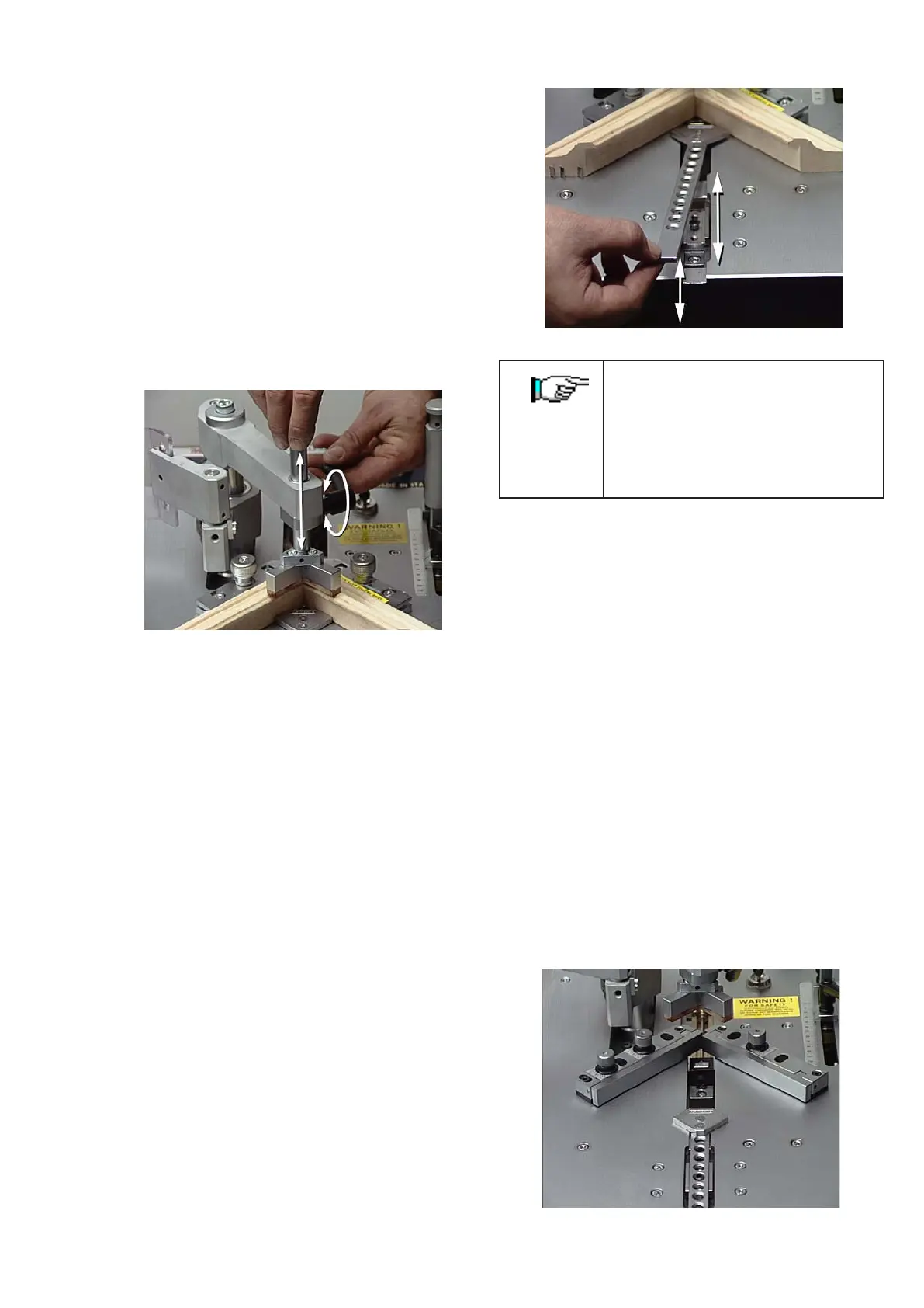
• Loosen the side clamp (see picture 14) by using the
handle and adjust the pressure pad height over the frame.
It is advisable to adjust the height between 5 and 8 mm
above the moulding to avoid any accidental fingers
crushing.
• Tighten the handle once you have reached the proper
position.
• Activate the vertical clamp by pressing halfway down
on the foot pedal and then press the control button or
pressing full down on the footpedal.
• Check that the mouldings to be assembled are properly
clamped.
4.9.3 Horizontal clamp adjustment
The Frontal Clamp (horizontal clamp) has a series of holes in
the flat bar, (see Picture 15) that lock into a peg in the front
channel. Lift the bar to take it out of its initial position and
make it move forward and backward.
To lock the bar it is sufficient to insert it into the proper peg
located in the center of the guide channel.
Proceed as follows to position the Horizontal Clamp correctly:
1. Remove the bar from the peg (lifting it by about 10-15
mm) and move it forward until it touches the mouldings
to be assembled.
2. Back the bar off until it drops into the next available
hole.
TAKE CARE: In case of continued use
without needing to remove the bar from its
position, it is possible to fix it into the peg
using the proper 6mm screw.
During machine transport, it is advisable to
lock the bar using the supplied knob.
4.9.4 Fences adjustment
The Mitre-Mite VN 42 is equipped with a fence composed
of two separate parts.
Each part of the fence (right and left) is equipped with a
knob that allows it to tilt a few degrees.
The use of this fence is suggested for working frames with
irregularities or small round parts on the external side.
If after the frontal clamping is engaged, the mitre of the
frame is not perfect, the tilting fence can compensate such
a fault.
The Mitre-Mite VN 42 can be used for 90°(4 sided frames),
120°(6 sided frames) or 135° (8 sided frames), by setting
the two fence supports properly(see pictures 16-17-18).
To modify the position of the two fence supports, proceed
as follows:
• Remove the external screw by using a 5 mm Allen
wrench.
• Loosen the internal screw and shift the fence until it
reaches the holes located on the working bench.
The exact position of the fence supports can be obtained
with the help of a special template, which was shipped with
your machine.
Make sure that the 120° or 135° angle formed by the two
supports is exactly centered on the internal vertex of V-
nails claw head.
 Loading...