48
10-5. Troubleshooting by inferior phenomena
No. Fault symptom Possible cause Explanation - Solution
1 Main remote controller
display is blank.
1. Thereisnopowersupplytomainremote
controller.
1. CheckLED2onFTC.(See"6.WIRINGDIAGRAM".)
(i)WhenLED2islit.
Checkfordamageorcontactfailureofthemainremotecontrollerwiring.
(ii)WhenLED2isblinking.
RefertoNo.5below.
(iii)WhenLED2isnotlit.
RefertoNo.4below.
2. Powerissuppliedtomainremote
controller,however,thedisplayonthe
main remote controller does not appear.
2. Checkthefollowing:
•DisconnectionbetweenthemainremotecontrollercableandtheFTC
control
board
•Failureofthemainremotecontrollerif“PleaseWait”isnotdisplayed.
•RefertoNo.2belowif“PleaseWait”isdisplayed.
2 “PleaseWait”remains
displayed on the main
remote controller.
1. "PleaseWait"isdisplayedforupto6
minutes.
1. Normal operation
2. Communicationfailurebetweenthemain
remotecontrollerandFTC
2,3.
Mainremotecontrollerstartupchecks/procedure.
(i)If“0%”or“50–99%”isdisplayedbelow"PleaseWait",thereisa
communicationerrorbetweenthemainremotecontrollerandtheFTC
control board.
•Checkwiringconnectionsonthemainremotecontroller.
•ReplacethemainremotecontrollerortheFTCcontrolboard.
(ii)If“1–49%”isdisplayed,thereisacommunicationerrorbetweenthe
outdoorunit'sandFTC'scontrolboards.
•CheckthewiringconnectionsontheoutdoorunitcontrolboardandtheFTC
control board.
(EnsureS1andS2arenotcross-wiredandS3issecurelywiredwithno
damage.(See"7.FIELDWIRING".)
•Replacetheoutdoorunit'sand/ortheFTC'scontrolboards.
3. CommunicationfailurebetweenFTCand
outdoor unit
3 The main screen
appearswithapress
ofthe“ON”button,but
disappears in a second.
The main remote controller operations do
notworkforawhileafterthesettingsare
changedintheservicemenu.Thisisbecause
thesystemtakestimetoapplythechanges.
Normal operation
Theindoorunitisapplyingupdatedsettingsmadeintheservicemenu.Normal
operationwillstartshortly.
4 LED2onFTCisOFF.
(See"6.WIRING
DIAGRAM".)
WhenLED1onFTCisalsoOFF.(See"6.
WIRINGDIAGRAM".)
<FTCpoweredviaoutdoorunit.>
1. The outdoor unit is not supplied at the
ratedvoltage.
1. CheckthevoltageacrosstheterminalsLandNorL3andNontheoutdoor
powerboard.(See"7.FIELDWIRING".)
•Whenthevoltageisnot220to240VAC,checkwiringoftheoutdoorunit
and of the breaker.
•Whenthevoltageisat220to240VAC,goto“2.”below.
2. Defective outdoor controller circuit board 2. CheckthevoltageacrosstheoutdoorunitterminalsS1andS2.(See"7.
FIELDWIRING".)
•Whenthevoltageisnot220to240VAC,checkthefuseontheoutdoor
controlboardandcheckforfaultywiring.
•Whenthevoltageis220to240VAC,goto“3.”below.
3.
FTCisnotsuppliedwith220to240VAC.
3. CheckthevoltageacrosstheindoorunitterminalsS1andS2.(See"7.FIELD
WIRING".)
•Whenthevoltageisnot220to240VAC,checkFTC-outdoorunitwiringfor
faults.
•Whenthevoltageis220to240VAC,goto“4.”below.
4. FTCfailure 4. ChecktheFTCcontrolboard.
•CheckthefuseonFTCcontrolboard.
•Checkforfaultywiring.
•Ifnoproblemfoundwiththewiring,theFTCcontrolboardisfaulty.
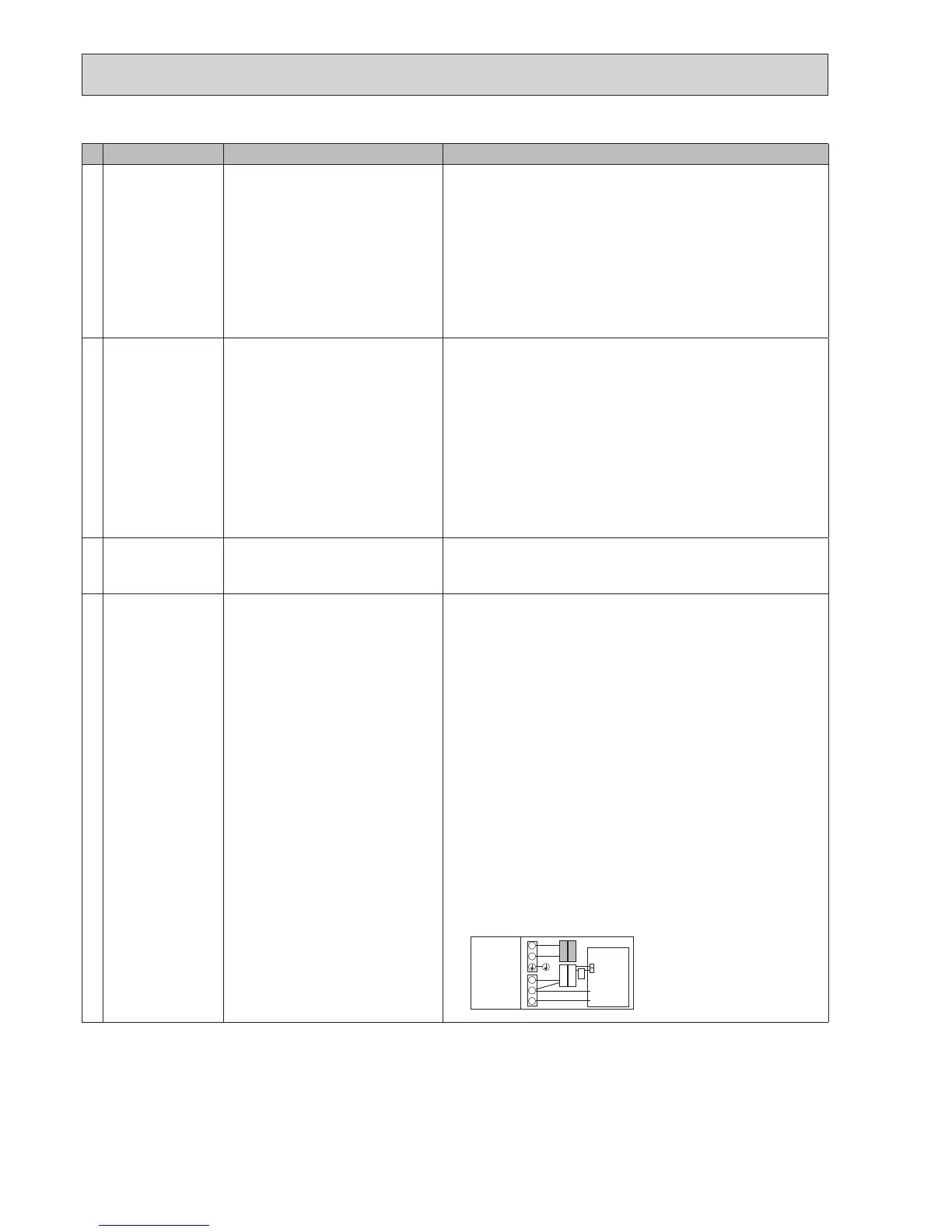
5. Faultyconnectorwiring 5. Checktheconnectorwiring.
•Whentheconnectorsarewiredincorrectly,re-wiretheconnectorsreferring
tobelow.(See"7.FIELDWIRING".)
S1
S2
S3
L
N
CN01
CN01
White
Hydrobox
control board
BLACK
YELLOW
YELLOW
BLACK
Initialsettings
(Powersupplied
byoutdoorunit)
 Loading...